This is the sixth (and last!) article of a series on the MakAir open-source ventilator, a project that I founded with friends, which was born at the beginning of the COVID-19 pandemic in early 2020. Think of this series of articles as a ledger of all that happened and all that was created. These articles could serve as the foundation of a project reboot in future years, in the event a similar pandemic was to emerge again.
This article explains how the MakAir software works. While a MakAir ventilator is rather simple in its pneumatics & electronics, its complexity lies in software. Pretty much like a Tesla, there exists tens of different MakAir hardware revisions and builds, though they all still receive software updates as of today. As the marginal cost of software tends to zero, keeping MakAir ventilators up-to-date with latest algorithms and safety improvements is basically free, even years after a ventilator unit was built.
The MakAir software has been split into two subsystems with different reliability guarantees: the ventilation firmware (it keeps the patient alive), and the control UI (it allows ventilation to be monitored, and settings to be adjusted). Let’s find out how they function and interconnect!
Setup Overview
If you are reading this article to get a quick overview of the MakAir software, you may first watch the following video, with which you will understand how to build the MakAir firmware, how to flash it, as well as which components run which part of the software.
Firmware & Ventilation Algorithms
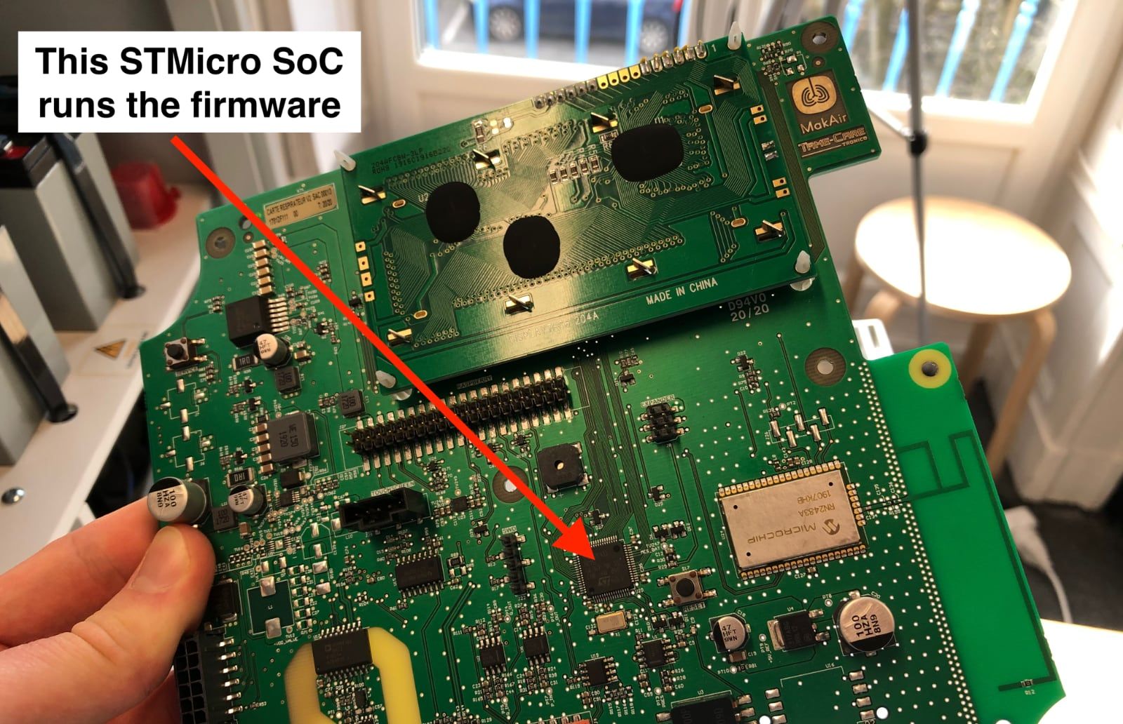
The firmware is the brain of the MakAir: it has the responsibility of keeping the patient alive, by providing enough air to their lungs (and not too much). The firmware centralizes input from all sensors (pressure & flow), and outputs commands to actuators (eg. pinch valves, blower, alarms). It implements ventilation algorithms, and ensures patient ventilation stays stable under the configured minimum targets and safety limits. Things are kept simple, meaning that the firmware has a single task, and does it in the most reliable way possible. If it fails at its mission, the patient dies, period.
Reliability comes from simplicity, as we can analyze all layers of complexity that are necessary for the system to function. It is the reason why the firmware does not run on any operating system. It is an embedded system built in C++, executed with a real-time computing constraint. The MCU it runs on is an ARM-based STM32F411 microcontroller, clocked at 100 MHz. Code ought to be as efficient as possible, in order not to overload this tiny processor.
The ventilation algorithms make an intensive use of Proportional–Integral–Derivative controllers (PID) when eg. calculating the angle of the pinch valves, resulting in more or less air passing in either the inspiratory or expiratory branch, until the sensor measurements stabilize to the desired target value.
Building the firmware
The firmware can be compiled from arduino-cli (though it does not target an Arduino board), in a single command:
arduino-cli compile --fqbn STM32:stm32:Nucleo_64:opt=o3std,pnum=NUCLEO_F411RE --verbose srcs/respirator.cpp --output output/respirator-production
This command produces a binary file, which can then be flashed onto the target board.
Flashing a firmware build
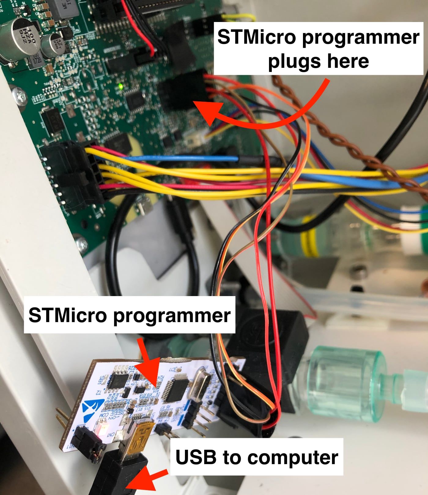
As explained in the video, flashing a MakAir motherboard (V3 revision), can be done by plugging a Nucleo F411RE programmer to the MCU JTAG port on the motherboard.
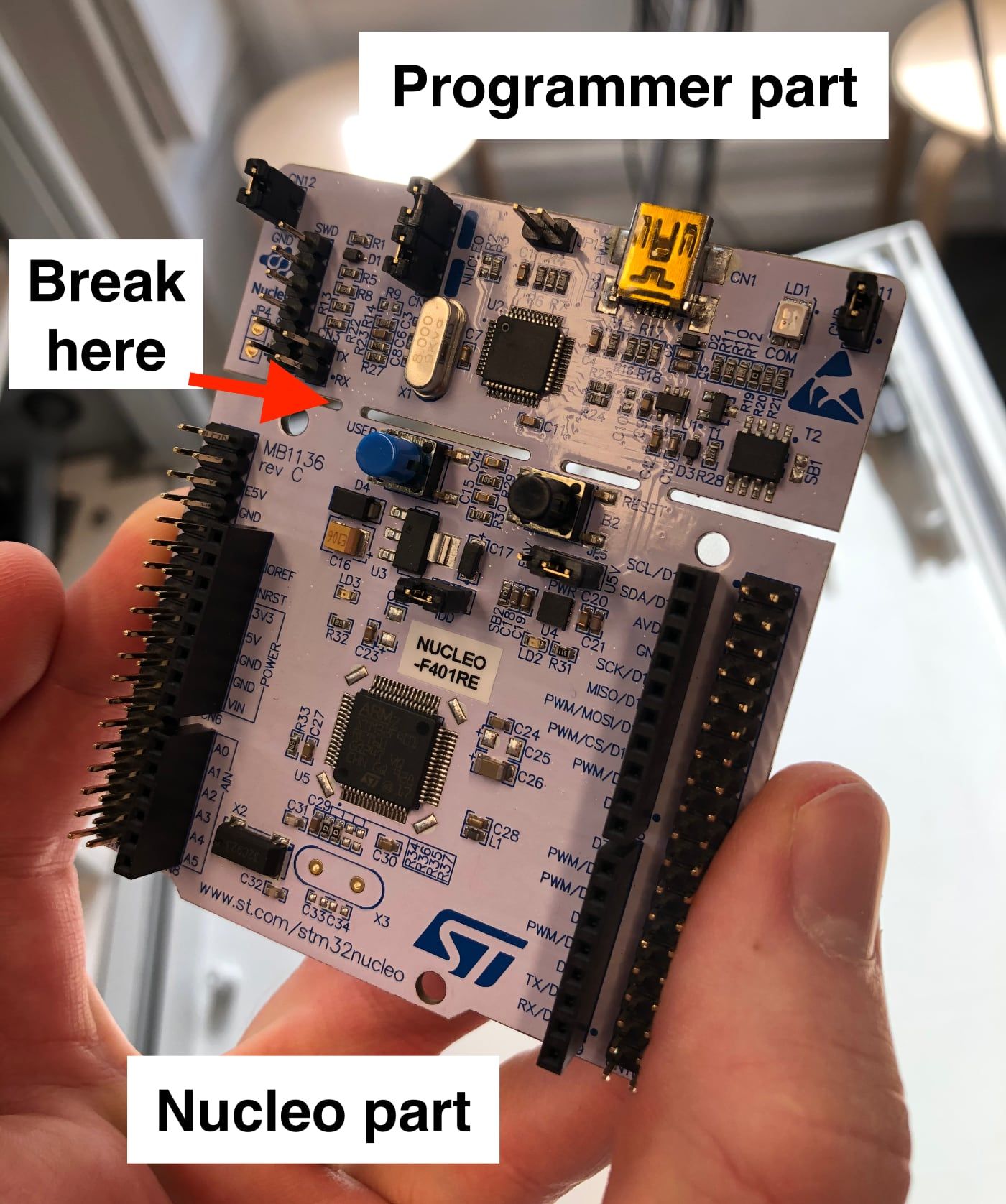
arduino-cli board list should show the programmer serial identifier to be used when flashing.Flashing can be done in a single command — once firmware binaries have been compiled — by passing the programmer serial port identifier for {SERIAL_PORT}:
arduino-cli upload --port {SERIAL_PORT} --fqbn STM32:stm32:Nucleo_64:pnum=NUCLEO_F411RE,upload_method=swdMethod --input output/respirator-production
Note that STM32Cube drivers are required.
Flashing the firmware this way is basically how we iterated on developing the firmware source code. We could simply leave our computer connected to the programmer, re-executing the compile & flash commands when needed. A flash operation only takes 1-2 seconds.
Hardware revision compatibility
During the first months of the project, the hardware team iterated on 3 motherboard revisions, tens of assemblies, packing different flow sensors, adding new components along the way. We introduced conditional compilation variables, in order, say, to be able to build the same firmware version for a Honeywell flow sensor or a Sensirion flow sensor.
This means that the current MakAir firmware supports a wide range of sensors and actuators alternatives, that perform the same function within the system (eg. measure air flow, or apply pressure on the air pipes). As well, some sensors such as the expiratory air flow sensor might be missing on certain hardwares, in which case the firmware will use an estimated value instead (based on measured pressure and measured inspiratory air flow).
Regulatory & safety
As use of firmware improvements on human patients is subject to regulatory approval, proper firmware versioning is an important matter. Simply put, a MakAir should only be used on a patient if the firmware version that was flashed onto its MCU has been certified.
Given the relative complexity of the control UI interface, and the potential safety issues that could arise in the event the control UI system was to freeze while the firmware is ventilating a patient — thereby preventing doctors from monitoring and adjusting settings — we implemented a control UI watchdog in the firmware.
As the firmware decides if the control UI board gets 5V power over the GPIO ribbon cable, in the event that the firmware has missed a heartbeat announcement from the control UI, it can decide to power cycle it, effectively rebooting the control UI systems and hopefully restoring normal function. This is an automated process, which the user would barely notice, as in such cases the UI would appear frozen for ~30 seconds. The Raspberry Pi watchdog code can be read from the firmware.
Note that we implemented this control UI watchdog preventively, ie. not as a patchy way to fix obscure freeze bugs we saw. With that said, you should understand that we never saw the control UI freeze yet. Better safe than sorry, though.
Control UI & Settings
The control UI is the presentation layer of the MakAir: it provides medical personnel with live measurements of the ventilation process, with a graph of pressure and flow metrics. As well, it lets the ventilator be configured from a touch panel, and shows alarms whenever an anomaly occurs.
The control UI is a graphical interface built in Rust, that runs on any UNIX operating system, with a stripped-down Linux target on MakAir ventilators.
The control UI does not run any ventilation algorithm, nor does it have direct control over ventilator actuators. The firmware handles the ventilation process, while the control UI communicates with the firmware over a telemetry protocol, and handles metrics and ventilation settings.
Building & running the control UI
Building the control UI is as simple as:
cargo build
It can then be ran using a sample telemetry recording with:
./makair-control --input=/path/to/makair-telemetry/records/v2/short.record
Video recording
A video of the control UI has been shot. This control UI was ran on a computer, and replays a telemetry dump that has previously been recorded with a test balloon.
Please note that the pressure and flow graphs do not reflect the ones you would see on a proper test lung, or a real human lung.
Project architecture & performance
The control UI is written in Rust, and runs on an OpenGL graphical backend provided by glium, with the help of conrod as to draw texts, images and shapes. It does not pack any heavy runtime; all potentially heavy components have been stripped down.
The control UI imports code from the makair-telemetry library, which exposes a simple programmatic interface which helps connect to the serial telemetry channel, and read payloads coming to this channel, as well as transmit commands (eg. change a setting).
The rest of the control UI is just reacting to telemetry events, maintaining a local store reflecting the state of the firmware and the underlying ventilation process, as well as handling user inputs (eg. screen taps). Different views are served to the user based on the state of the ventilator unit (eg. stopped, running, in error, in a setting modal, etc.).
As the UI would be running all the time over the course of 2 weeks when ventilating a patient, we took special care to prevent memory leaks (the RAM usage of the UI is stable at 36 MB on a 32-bit SoC), as well as reduce CPU and GPU usage to a bare minimum.
Indeed, as the interface needs to show graphs in real-time by refreshing the screen at 30 frames per second, non-optimized code could result in elevated CPU usage, which in turn would cause the CPU to heat up. As we opted for the passive cooling of the control UI board (a Raspberry Pi 4), we made sure to keep CPU usage low to a mean ~30% of 1 ARM CPU core out of the 4 available. Our measurements indicate that in a 20°C room, the CPU did not get hotter than 45°C (that is quite satisfying!).
On the importance of UX
Starting with MakAir hardware V1, ventilation settings could be changed with physical buttons, mounted on the motherboard. As the project grew, we added so many settings that they could not fit on hardware buttons anymore, unless we transformed the ventilator to look like a plane cockpit. Thus, we made the choice to move all settings to the touchscreen UI, effectively deprecating hardware buttons.
In practice, using a touchscreen for controls is much more versatile, as the ventilator user interface becomes a single clean flat surface, that can be easily disinfected after use; contrasting with the bumpy button-based facade. As well, before the touch UI was mounted, we had to design a front panel printout for each targeted user language, whereas the UI can be translated virtually in any language, and makes MakAir hardware country independent.
In real world situations, a MakAir ventilator might be placed meters away from where medical personnel stand. Whenever a quick ventilation measurement reading is needed, people should be able to see the text shown on screen from meters away. This forced us to use quite a large font size. Similarly, we had to adapt button sizes and implement double confirmation prompts everywhere, as doctors may interact with the ventilator while wearing gloves, sometimes in emergency situations.
Efficient real-time graph rendering
The control UI renders two independent graphs at the same time: pressure and flow. Each graph draws data sampled at a rate of 100 points per second, and is refreshed at 30 frames per second.
To render graphs, the control UI is using the plotters library, written in Rust. plotters renders its plots through a rendering backend, which can be customized. When we started up the control UI project, the only plotter that could be interfaced with our conrod drawing backend was the Bitmap backend, meaning plotters had to use a CPU-based rasterizer do draw each graph pixel-by-pixel, and feed it as an image to conrod for drawing.
As expected, this CPU-based rendering method did not allow us to draw two graphs simultaneously on the same CPU core, the control UI rendering loop being mono-threaded. A single graph consumed nearly 70% of one CPU core at 30 FPS, thus dramatically reducing the FPS if we were to draw a second graph (140% CPU).
This is where we decided to build a native plotters backend for conrod, named plotters-conrod. Such a backend would draw using conrod shape primitives instead, which in turn would use OpenGL as to render them from the GPU.
This rendering method has proven to be much more efficient, as it freed CPU resources, delegated all plotting work to the GPU, allowing two plots to be rendered from a single thread at 30 FPS. As a bonus, the GPU performs vector graphics in contrast to the CPU raster graphics, meaning that antialiasing could be enabled at no cost, producing much better looking graphs.
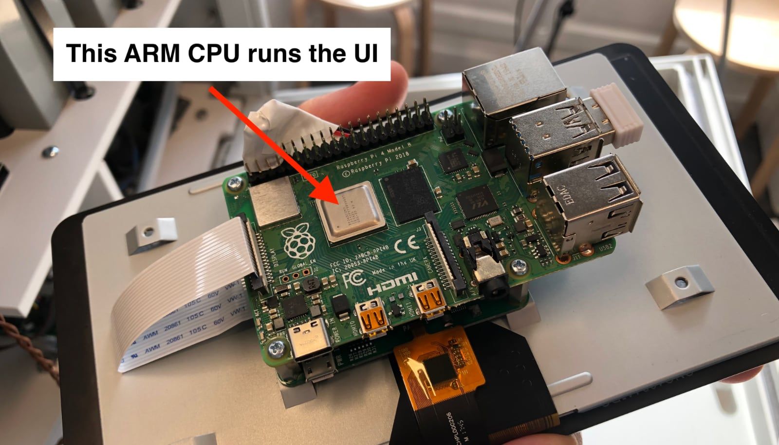
Hardware running the UI
The control UI runs on a Raspberry Pi 4, equipped with 1 GB of RAM (though 128 MB RAM only would do as well). The Raspberry Pi is connected to a 7” Raspberry Pi Touch Display.
The control UI requires a single ARM core, running in a low-frequency mode through the powersave CPU governor, ensuring the CPU stays cool (600 MHz).
As we were limited in time, note that we made the choice to lock the control UI drawing area to the 7” touch display native resolution, that is 800 x 480 pixels. If a larger or higher density screen was to be used, the control UI source code would need to be adjusted to upsize the interface, or make all interface elements upsize dynamically based on their parent container size.
Note that we share prepared system images that can be readily flashed to a 8GB microSD card. This will get you a working Raspberry Pi system and control UI in a matter of minutes. The system image is available in a special large files repository.
On a deeper integration of systems
For now, any firmware update must be applied by plugging in a STM32 programmer to JTAG pins on the motherboard. While keeping a MakAir firmware up-to-date is important, this maintenance operation can be quite tedious and complex for some MakAir end-users.
The last motherboard revision exposes an USB port and packs an integrated programmer on that port, which can be used by the control UI running on the Raspberry Pi to initiate a firmware update sequence. The MakAir team is therefore thinking about integrating a signed archive of the firmware within the control UI binary. This would allow the UI to show a new maintenance tab, letting the user flash new firmware code on the motherboard.
On its end, the UI could show a “check for updates” button in the maintenance tab, and perform an OTA update whenever the MakAir ventilator gets connected to the Internet over the Ethernet port on its back side. Updating the UI from the Internet would result in the control UI restarting to its new version in a matter of seconds. Upon booting up, this new UI runtime could prompt to flash the new firmware build it contains on the MCU, if it detects that an outdated firmware version is running on the motherboard.
Note that the current Linux image that the control UI runs on is based on Arch Linux. Running on a desktop/server-grade Linux distribution is sub-efficient, as it packs a lot of useless binaries and kernel modules. We have a project to build a smaller, minimal Linux image. This would help strip down control UI boot time from ~20 seconds to ~5 seconds.
Telemetry Protocol
The telemetry protocol is the glue binding the firmware and the control UI together. We designed this protocol to be as lightweight and parser-efficient as possible, as the firmware, that sends the most protocol frames, runs on a rather slow ARM MCU.
Telemetry protocol frames are transmitted through a RX/TX serial channel, meaning it is bidirectional. The control UI is able to transmit protocol frames to the firmware to change ventilation settings, while the firmware sends over a stream of telemetry frames as to let the control UI show beautiful real-time pressure & flow graphs.
Telemetry frames get serialized/deserialized by a dedicated telemetry library, which abstracts the wire protocol into more expressive Rust code.
Telemetry frame types
The telemetry protocol is made of predefined frame types, that can either flow from the firmware to the control UI, or from the control UI to the firmware.
Frames sent from the firmware, as of protocol V2:
BootMessage: the firmware announces that it has finished its boot sequence, sensor self tests and is now ready for use (code);StoppedMessage: ventilation is stopped, though all settings get broadcast at a periodic interval (code);DataSnapshot: ventilation is active, instant sensor measurements are reported every 10 ms (code);MachineStateSnapshot: ventilation is active, all current settings are reported at the end of each respiratory cycle, which should be every 2-3 seconds (code);AlarmTrap: an alarm has been triggered, and should be displayed on screen, eg. ventilator is on battery (code);ControlAck: the firmware acknowledges that it updated a setting that was committed by the control UI via aControlSettingframe (code);FatalError: the ventilator raised an error and is thus not usable in this state, eg. sensor self tests failed on boot (code);EolTestSnapshot: sent when the manufacturer performs end of line tests, ie. before a MakAir is validated and packaged (code);
Frames sent from the control UI, as of protocol V2:
ControlSetting: the control UI commits an updated setting to the firmware, and waits for an acknowledgement via aControlAckframe (code);
Protocol versions & backward compatibility
As the firmware and control UI might be updated separately, where the control UI could be updated more often than the firmware — due to new firmware versions being subject to regulatory approvals — it is critical that a firmware running an older telemetry protocol version is still able to feed its data to an up-to-date control UI.
The telemetry protocol has this covered, as all telemetry frames put on the wire get tagged with a version number. Upon receival, a protocol V1 frame can thus be directed to a different parser than a protocol V2 frame, albeit ultimately producing a consistent, common, data structure that is usable by the control UI. In fact, the control UI does not even care which telemetry protocol the firmware is speaking, as this is abstracted by the telemetry library. This means that the control UI can use the same data structures for different protocol versions.
Still, support for older telemetry protocol versions might be dropped when they become too legacy. For any telemetry version support pulled from the telemetry library, the control UI handles this gracefully. In the event that an unsupported telemetry frame gets received, the UI will show an error message prompting the user to update the ventilator firmware to a newer version.
Protocol flow example
As an example of a normal protocol flow, when booting up a MakAir ventilator running telemetry protocol V2, this is what you would see if you were to tap the serial wire:
- The firmware announces it has booted and that it is now ready with a
BootMessageframe; - As the ventilator unit is not running yet, the firmware sends
StoppedMessageframes at periodic intervals; - The user starts tapping on the touchscreen and adjusting ventilation settings: what follows is a request-response exchange of
ControlSettingandControlAck; - The user starts the ventilation unit, another
ControlSettingandControlAckexchange occur, withControlSetting::RespirationEnabledset to value1; - The ventilator is now running, it starts broadcasting a
DataSnapshotframe every 10 ms, with measurements from its sensors; - At the end of each ventilation cycle (that is, at 15 cycles per minute, every 4 second), a
MachineStateSnapshotis announced, as to re-synchronize any setting that may have gone out of sync on the control UI (eg. if the UI was rebooted when the ventilator was already running); - The user unplugs the ventilator to move the patient, an
AlarmTrapevent is raised, with alarm code31(forAlarmCodeDescription::PowerCableUnplugged), telling the UI to show an alert that the ventilator is now on battery; - (…)
- The user unplugs the patient, and stops the ventilator, a
ControlSettingandControlAckexchange occur, withControlSetting::RespirationEnabledset to value0; - The ventilator is now stopped, the firmware sends
StoppedMessageframes at periodic intervals (DataSnapshotandMachineStateSnapshotare not sent anymore);
Telemetry recordings & replays
In order to help debug telemetry frames, as well as provide replays for library and control UI development purposes, telemetry frames can be dumped in a record file, in which binary telemetry messages are encoded in Base64. Such a record file for the telemetry protocol V2 can be found there.
Telemetry records can be easily replayed on a computer, with the help of the control UI, in a single command:
makair-control --input=/path/to/makair-telemetry/records/v2/short.record
The ability of replaying records lets MakAir developers debug records from eg. clinical trials, where ventilation anomalies or particular events would be reported by medical personnel, and developers would then try to understand what happened, eg. “is this strange ventilation behavior related to a doctor changing a setting and making a mistake in the decision?”.
If an USB key is plugged on any USB port on the board that runs the control UI, telemetry frames will be dumped on a record file on that USB key. The USB key can then be pulled from the ventilator and its contents analyzed and replayed, much like a flight recorder on a plane (ie. black box).
Firmware Simulator
The firmware simulator is one of the latest experiment of the MakAir project. It basically integrates the firmware as a library, and simulates hardware components, namely sensors (pressure & flow sensors) and actuators (pinch valves). It models the effect of the patient lung on air pressure and air flow.
The firmware simulator was built with three goals in mind:
- Let developers & UI designers contribute to ventilation algorithms and the control UI, where they have no access to a MakAir ventilator hardware;
- Let theoretical researchers in ventilation algorithms implement their algorithms, and test them out on an actual ventilator & lung model;
- Package the simulator, firmware and control UI in an app that could be used by trainees in medical schools to learn how to use a ventilator and ventilate a (simulated) patient, where the lung model could be chosen from a list, in order to simulate a wide range of pathologies (from a healthy adult to an ARDS patient);
We have also managed to run the firmware simulator with its attached control UI on a cloud server, running a VNC server. We exposed a VNC client on a Web page, which we shared to doctors as to demo the MakAir user interface and firmware. Through this demo server, doctors could interact with the simulated MakAir ventilator, right from their Web browser. They could change ventilation settings and evaluate the quality of our ventilation algorithms in comparison to commercial ventilators.
This experiment was a huge success, which suggests that we should scale this “marketing” method as a way to showcase the robustness of our ventilation algorithms, in turn to build trust in the MakAir software, which could ultimately lead to more doctors using MakAir ventilators on patients.
Closing Notes
This article was the sixth (and last!) of a series on the MakAir story, providing insider details on the project, medical knowledge on the state of the art of mechanical ventilation, as well as in-depth engineering explanations on how we designed our ventilator algorithms and electronics. The overall goal of this series of articles is to build the legacy of the MakAir project.
While our first software revision was only made of a firmware running on an Arduino board, trying to reproduce the pressure curve as close as possible, it was a matter of days before we moved over to a more robust PID-controlled algorithm, running on a STM32 MCU. We added a touchscreen interface to the system thereafter, improving user experience and bringing ventilation monitoring capabilities.
We are now iterating on the firmware and control UI to improve safety and UX, as well as adding easy maintenance features such as the ability to perform OTA updates of the firmware and the control UI, right from the touchscreen. We are trying to improve the developer experience as well, with the inception of a firmware simulator, that mimics a MakAir hardware running with simulated physics, which lets developers contribute from their laptop, anywhere in the world.
Also, I’m always available to answer questions, please ask them in the comments section of this article!
🇵🇹 Written from Lisbon, Portugal.