This is the fifth article of a series on the MakAir open-source ventilator, a project that I founded with friends, which was born at the beginning of the COVID-19 pandemic in early 2020. Think of this series of articles as a ledger of all that happened and all that was created. These articles could serve as the foundation of a project reboot in future years, in the event a similar pandemic was to emerge again.
This article explains how the MakAir electronics work. Electronics are the center piece of the MakAir ventilator, as they interconnect software & algorithms with pneumatics & actuators. As well, they handle all user controls, eg. changing an option on the touchscreen. While early MakAir prototypes ran on development boards, we quickly moved to custom-built production-ready boards, allowing us to fit all required components on a single PCB.
Assembly Overview
If you are reading this article to get a quick overview of the MakAir electronics, you may first watch the following video, with which you will understand what makes the MakAir electronics, and how they work together.
The Big Picture
We have described the pneumatics system in the previous article, which is made of passive components (eg. pipes), as well as active components (sensors and actuators) that need to be controlled by some central brain. This is where electronics come into play.
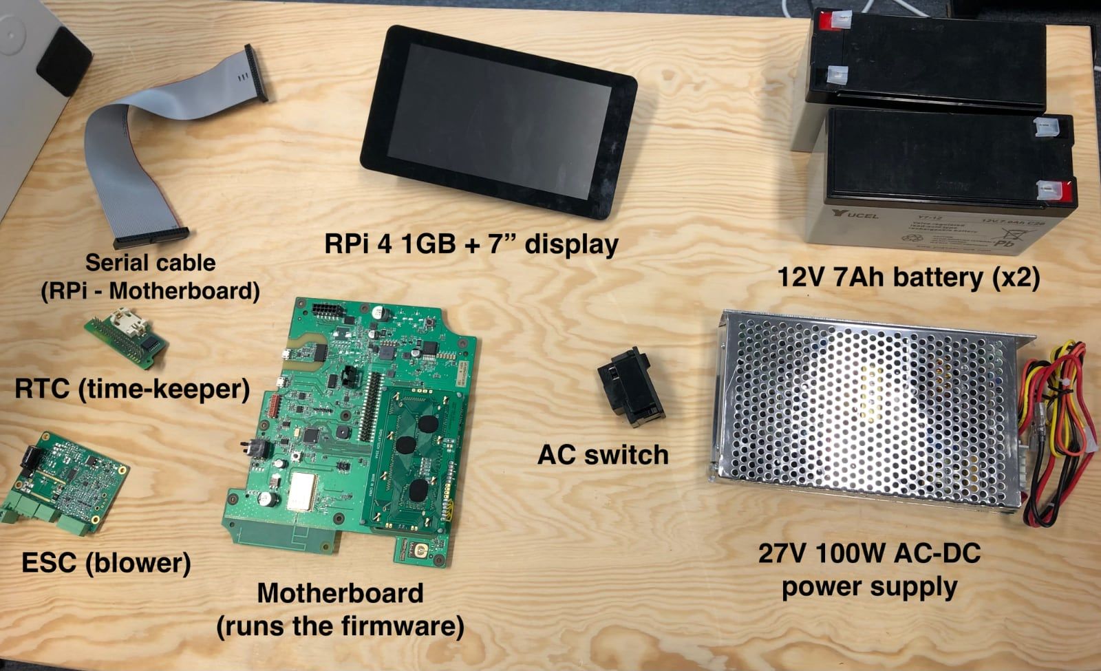
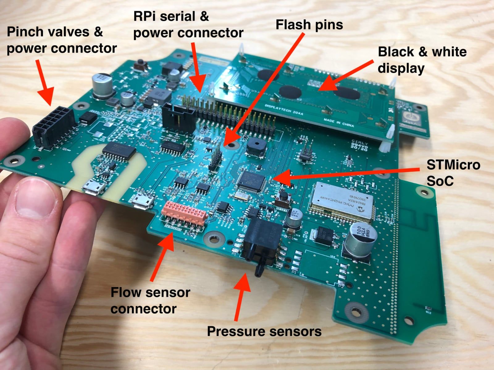
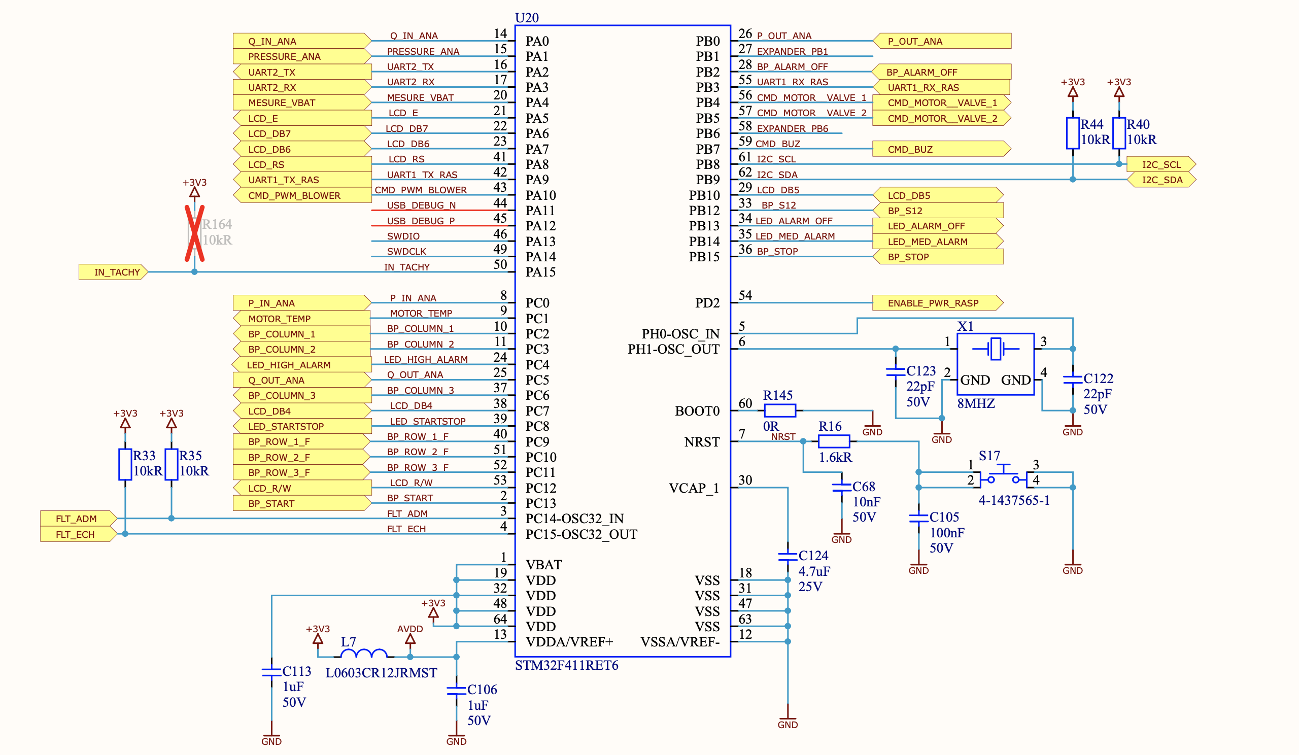
The MakAir ventilation software — we call it the firmware — runs on a custom motherboard, that houses a STMicroelectronics STM32F411 microcontroller (or MCU), as well as input/output ports for sensors and actuators. This piece of electronics is the sole responsible for running the ventilation software, which acts — in worst cases — as a replacement diaphragm for the patient lungs for approximately 2 weeks. It must not fail, or the patient will be in serious trouble: life-threatening style, until medical personnel intervenes.
We made sure to choose electronic components that were known for their reliability and stability, as well as simplicity. For instance, the MakAir motherboard does not run any operating system; the MakAir Firmware runs directly on the CPU with no abstraction layer (our firmware boots at memory address 0).
On the other hand, as doctors are used to modern commercial ventilators that can be monitored and configured over a large touch screen, we decided to add one to the MakAir as well. This large touch screen requires a complex desktop-class CPU, GPU, video drivers, as well as an operating system, which make this device less reliable, by design — unless we were to write image frames in the framebuffer, skipping abstraction layers. We chose to use commodity electronics to build this part of the ventilator, as the market is already full of highly-efficient ARM-based boards. In this specific case we chose the Raspberry Pi 4.
This touchscreen computer runs the MakAir Control UI, which talks to the firmware via the MakAir Telemetry Protocol, over a bidirectional serial connection. The MakAir Telemetry Protocol acts as the interface between the MakAir Firmware and the MakAir Control UI, and lets the touch UI commit ventilation settings changes, while the firmware feeds the UI with real-time ventilation metrics, that are used to show live graphs of air pressure and air flow.
It is particularly important that those two computing units are independent, as one is clearly more critical than the other, pretty much like how the drive computer and the multimedia computer are split in a Tesla. When a failure on the touch UI computer would be inconvenient at worst, a failure on the ventilator motherboard is definitely a life-threatening situation.
All those power-hungry electronics could not work without proper DC current. Given how unstable the AC power grid can be in certain areas of the world, and that a patient may need to be moved rooms or transported on the road, any ventilator must provide backup power in case AC is unplugged or fails. The MakAir comes equipped with a 60W AC-DC 24V power supply, capable of powering the ventilator and charge the two onboard 12V 7Ah lead-acid batteries at the same time. Those batteries can provide backup power to the ventilator for up to 4 hours.
Motherboard
The MakAir motherboard is a custom-built printed circuit board, dedicated to running the firmware & ventilation algorithms, and allowing software to gather realtime data from sensors and control pneumatic actuators. It also serves other functions, such as handling user input through hardware buttons, or emitting high-pitched noises through a buzzer whenever an alarm is triggered.
All credits for the MakAir motherboard design go to Vincent Le Cunff from Tronico.
Motherboard revisions
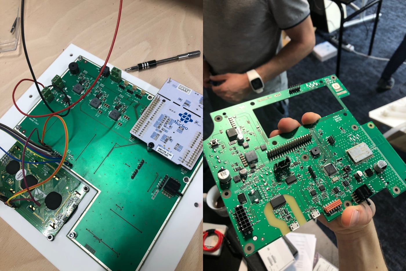
While initially the MakAir team has been working on development boards — an Arduino Uno, then a Nucleo F411RE — it was soon time to design our own motherboard PCB, integrating a STM32F411RE MCU as on the Nucleo. That motherboard went into 3 design revisions.
In addition to running the firmware, the motherboard provides user interaction via hardware buttons, though we are slowly deprecating those in favor of the touch UI. As well, an alarm buzzer and LEDs are mounted on the board to provide audible and visible feedback whenever an alarm is raised, eg. for instance a target pressure is not reached, which is abnormal and thus for which human intervention might be required. Here as well, we may deprecate the LEDs in favor of the touch UI, though the buzzer is staying.
In the latest revision, we added a LoRa wireless module, allowing the firmware to broadcast telemetry data to a receiver device. Though unused at the moment, we got the idea that building a centralized monitoring dashboard could be much appreciated in pandemic situations, where too many patients would be ventilated under the oversight of too few doctors. Hundreds of MakAir ventilators could be used at the same time, with their alarms and metrics being transmitted realtime to a “control center” room in the hospital. LoRa (for Long Range), is capable of transmitting information with a range of 10 kilometers, at a low data transfer rate (from 0.3 kbit/s to 27 kbit/s). It doesn’t require relaying infrastructure like WiFi, as in our use case it is simply made of N transmitters (MakAir ventilators) sending to 1 receiver (MakAir monitoring dashboard).
Note that a black & white display is mounted on the motherboard. While today’s MakAir ventilators use a touchscreen, the monochromatic screen is still used during the production process to perform end-of-line tests & calibrations. This display will go away in next motherboard revisions, in a similar fashion to the hardware buttons.
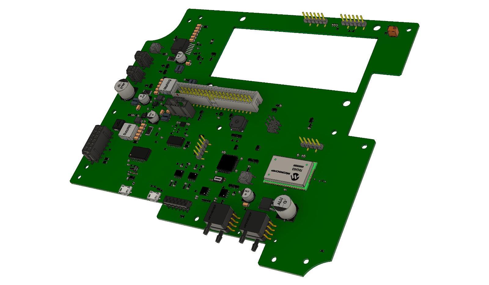
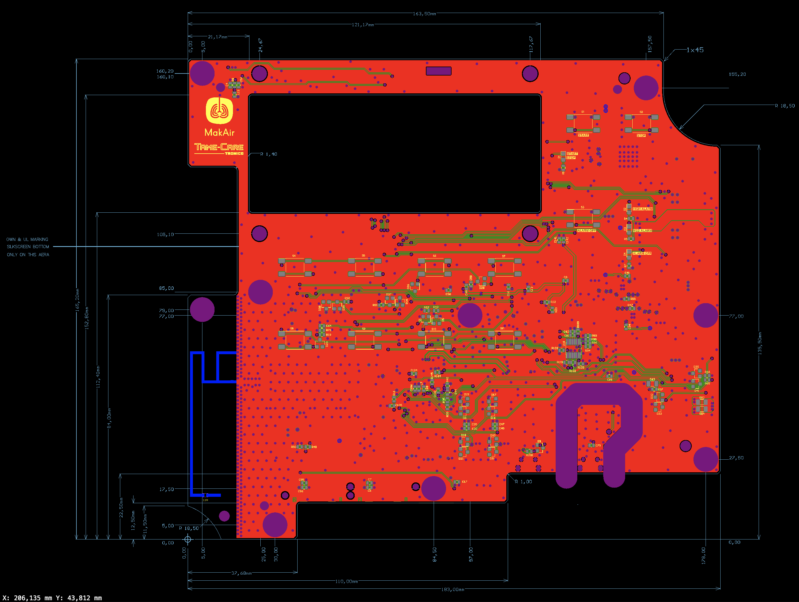
Motherboard schematics
The electrical schematics for the motherboard are open-source, which let anyone make a list of required components, or reproduce and improve the existing motherboard with specialized electronic design software.
As well, the motherboard Gerber files available in our repository. They can be used to send our current design to PCB factories for production.
The list of components to solder on the PCB is available through the schematics. They can be applied on the PCB by a pick-and-place machine. You can also use the Bill of Materials that we published to proceed with bulk-ordering all required components.
Programming interface
In order to flash a firmware to the motherboard, a programming interface is required. The MakAir motherboard offers two ways to flash a firmware: either use a STM32 programmer on JTAG ports, or commit it over USB. We tend to prefer using the programmer from the Nucleo development board, which we broke apart from a Nucleo board, then we connect it to the motherboard JTAG ports, and finally we plug it on a computer over USB and upload the firmware with STM32Cube.
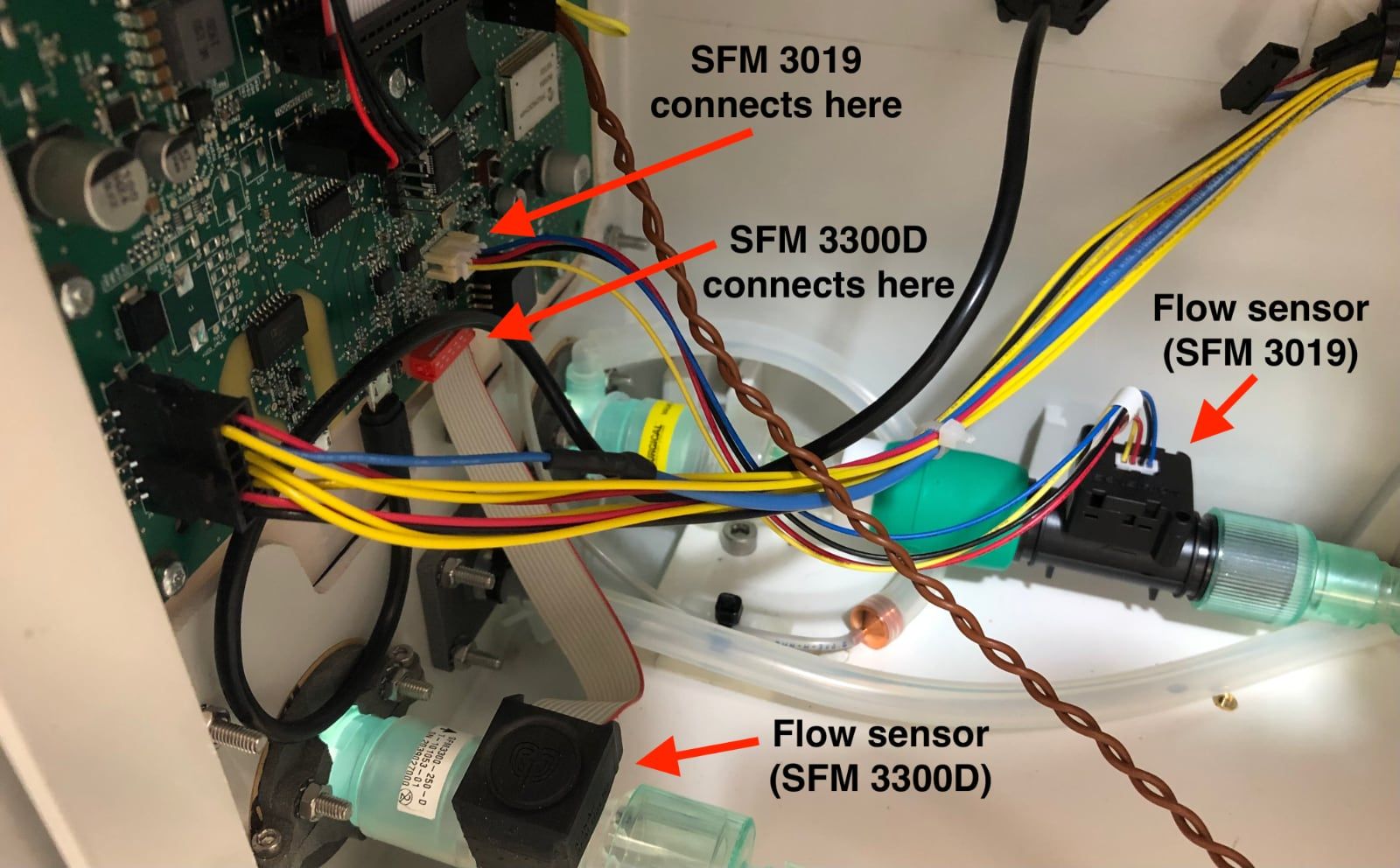
Wiring to sensors & actuators
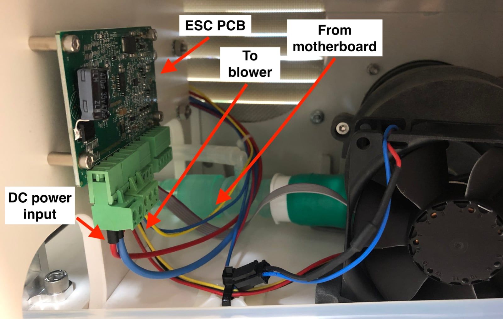
In order to connect all sensors (eg. flow sensors) and actuators (eg. pinch valves, blower), a cable harness should be built, and would connect to the motherboard via a single connector. Note tough that the two flow sensors connect to an individual extension port each.
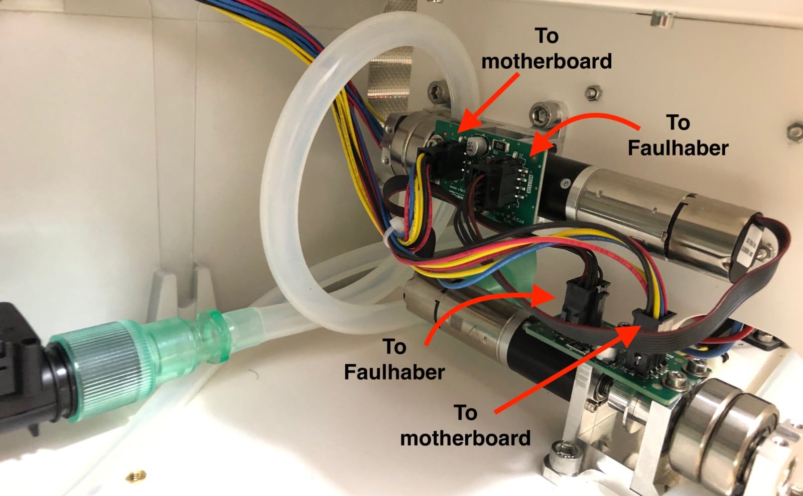
The blower, while controlled by the motherboard, is not directly connected to it. As the motherboard would be sending a PWM signal with the target blower speed, this target value would need to be converted to a 3-phase signal that would make the blower DC motor spin. That is the job of the ESC board, which takes in a speed target via a PWM signal, as well as a power source (high amperage line).
Control UI
The MakAir Control UI runs on a second computer board, which is connected to the motherboard over a GPIO ribbon cable. As it might be less reliable than the motherboard due to its advanced hardware and software complexity, the probability of failures is much higher, and thus in the event it fails, ventilation algorithms must still go on.
System design
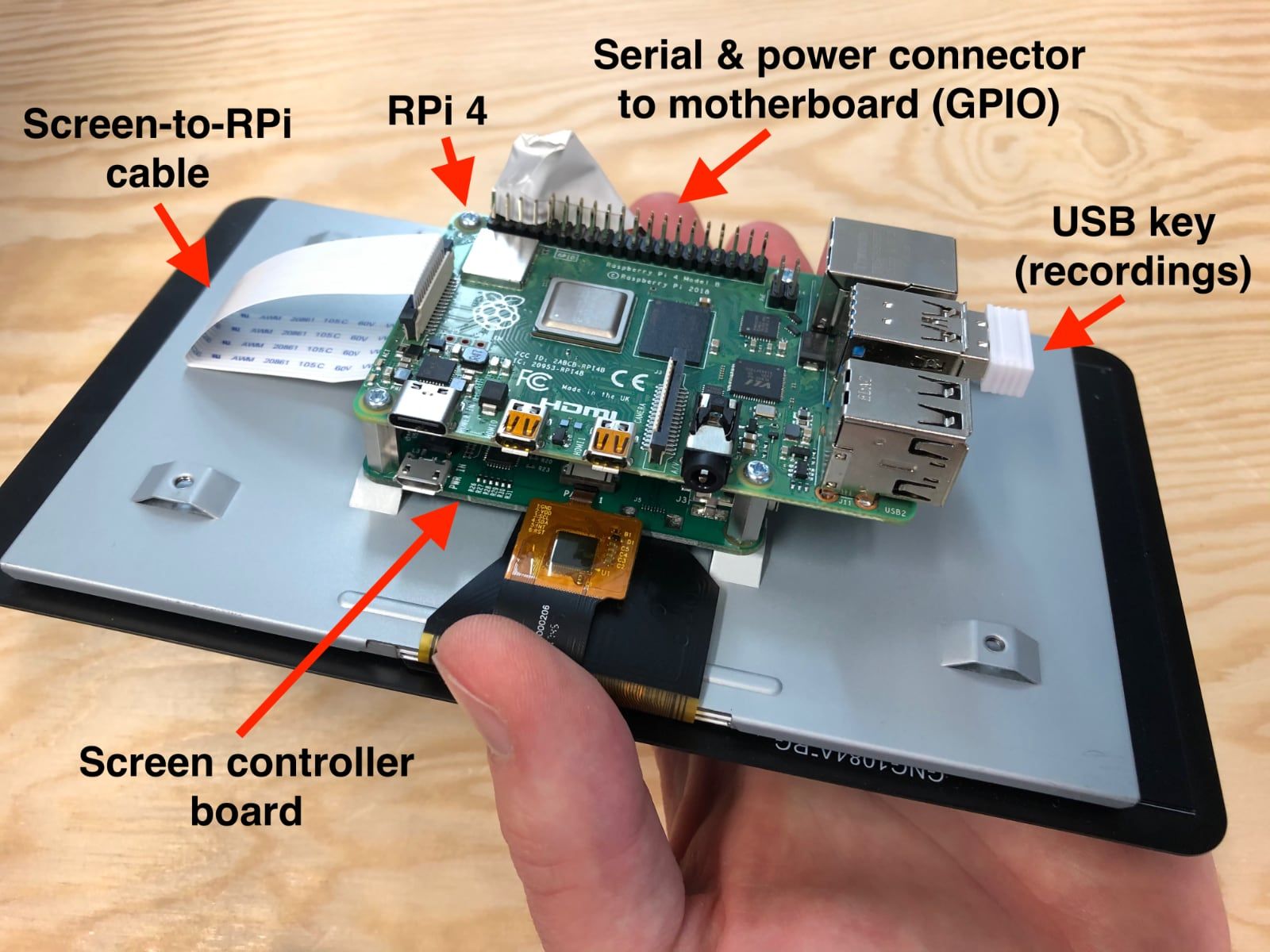
We chose a Raspberry Pi 4 to run the Control UI software, which is plugged to a 7” Raspberry Pi Touch Display.
The Raspberry is powered by the motherboard itself. In order to address possible failures, it sends periodic “heartbeats” to the firmware, which is able to run a power cycle sequence if it misses an heartbeat announcement, effectively rebooting the Control UI computer electrically.
Ventilator black box
When testing new ventilation algorithms on a live patient, or during clinical trials, anomaly events might be reported by medical personnel and may require further investigation by software or hardware engineers.
The Control UI computer allows for an USB key to be plugged on one of the four USB ports of the Raspberry Pi. Whenever an USB key gets plugged in, the system detects it and starts recording telemetry logs. This USB key effectively acts as a “black box”.
Those telemetry logs can be retrieved later on, and replayed on a simulated Control UI on a computer. It also indicates the exact date and time at which an hardware button was pressed to adjust a setting, eg. increase a target pressure value.
Note that telemetry recordings are actually a raw dump of the very same telemetry protocol used over serial between the motherboard and the touch UI.
Keeping track of time
As the Linux system running on the Raspberry is not connected to the Internet, and thus cannot reach a NTP server whenever it boots up, its internal clock will lose track of time whenever the MakAir is powered off. Recovering the actual date and time can be important when recording ventilation logs to the ventilator black box (ie. the USB key).
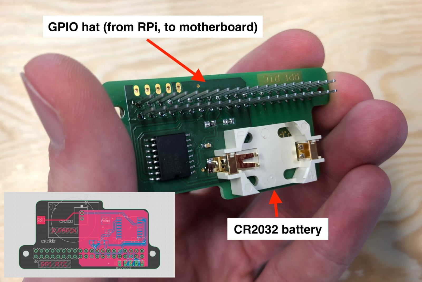
To address this issue, we designed a custom Raspberry Pi RTC module that plugs to the Raspberry Pi GPIO port (RTC comes for Real-Time Clock). It can be polled by the Linux system during boot to retrieve the actual date and time from the RTC hardware clock. A CR2032 battery powers the RTC chip, which keeps track of time when electronics are powered off.
The source files for this board are open-source. Credits for the RTC PCB design go to Pierre Papin, from the MakAir team.
Power & Battery
Mechanical ventilators, while mostly used stationary and thus plugged to AC power, must allow medical personnel to continue ventilating the patient as it is being moved from place to place, and thus should be able to fallback to battery DC power.
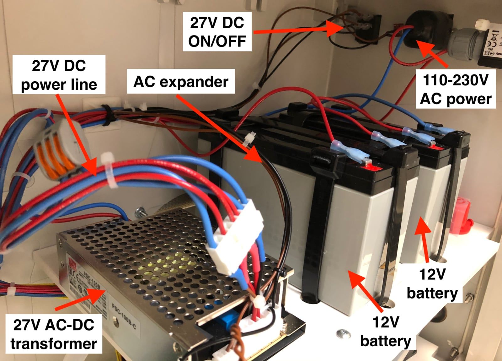
The MakAir ventilator is powered by a medical-grade Mean Well RPS-60 24V power supply. It feeds the electronics with a stable 24V DC voltage at 2.5A maximum, while at the same time charging the two 12V 7Ah lead-acid batteries.
Addressing current peaks
When running, all ventilator components put together draw a mean current of 1.2A (~30W at 24V), which the power supply can happily deliver.
Whenever algorithms decide to increase the blower speed — either due to a change in lung compliance or in the target tidal volume value — the blower may draw too high of a current than the power supply is able to deliver, for a few milliseconds. This event can be quite catastrophic if the batteries are not available to deliver the spare current, as the voltage would drastically drop within the system, which would trigger a general system reboot.
During clinical trials, unfortunately such an event occurred due to medical personnel starting ventilating a patient without connecting the batteries inside the MakAir. After some hours of successfully ventilating the patient, a sudden blower speed increase event occurred, to maximum throttle — due to the patient coughing. As you’d expect, the ventilator power cycled itself, which hopefully the medical team handled quickly enough.
In order to address this — let’s admit it, rare case — we implemented a progressive blower speed ramp up algorithm, spreading the speed increase over a timeframe of 2-3 seconds. This has been tested to limit the current draw of the blower to an acceptable level, effectively addressing the issue.
Choosing lead-acid over Lithium-ion
Given the superior energy density of Lithium-ion batteries over lead-acid, one might be tempted to choose them over the latter.
While more modern and more compact than their older counterparts, Lithium-ion batteries require more electronics to operate in a safe way; they require a Battery Management System (BMS), increasing complexity and cost.
In comparison, lead-acid batteries are happy being wired directly to their power source (the AC-DC transformer) and their load (the motherboard, blower and others).
As well, lead-acid batteries are very common and affordable. The 12V batteries used in the MakAir ventilator can be found in any battery shop, and can even be scavenged on scooters. In comparison, Lithium-ion batteries are harder to source. This comes especially true as you go to remote area throughout the world.
Adding to that, airline safety regulations regarding the transportation of Lithium-ion batteries is quite stringent. Given that in pandemic situations MakAir ventilators could be shipped by thousands in cargo planes, Lithium-ion seemed like an obvious no-go.
Estimating the state of charge (SoC)
Being a medical ventilator, the MakAir must be capable of functioning on battery while ventilating a patient for at least 30 minutes. Our measurements indicated that the MakAir ventilator could go well above that, reaching the 4 hours autonomy mark.
In order to provide the end-user with a quick snapshot of the battery state of charge (SoC) through the UI, expressed in remaining battery percentage (eg. 93% battery left), we needed to characterize the battery discharge rate on a known load (eg. 1A).
The only reading letting us approximate the state of charge of the battery is a live voltage measurement. This voltage measurement, while indicative, can be very unreliable, as slight voltage drops can occur eg. if the blower ramps up and pulls more current, which could result in an approximated SoC that would be much lower than it really is. A more reliable voltage measurement would be an open-circuit one, performed after letting the batteries cool down a bit and giving time for their chemistry to stabilize. Note that in practice, we cannot do so, as the ventilator is running non-stop.
After trial and error, as well as performing a full discharge characterization of the batteries of a MakAir under a typical load, we came up with a software-based “BMS” capable of estimating the SoC at any time, based on voltage readings and approximated current draw of the system given the blower speed. You can read its source code here.
Detecting when AC power is unplugged
The MakAir UI should show an alarm whenever the ventilator is unplugged from AC power, and is thus on backup power.
As the system voltage is a bit higher when AC power is connected than when on batteries, we traditionally used live voltage measurements to speculate as to which power source was in use.
This method was not very reliable; it sometimes reported that the ventilator was still on AC, although it was running on battery power (SoC at 100%).
In order to address this (slight) issue, we drew a cable from the power supply to the motherboard, which we call the expander. This cable reports the power supply output DC voltage, independent from the batteries. That DC output would be 0V if the power supply was not powered over AC. The firmware can then read this voltage value, and use it as a high/low boolean state to show which power source is being used.
Closing Notes
This article was the fifth of a series on the MakAir story, providing insider details on the project, medical knowledge on the state of the art of mechanical ventilation, as well as in-depth engineering explanations on how we designed our ventilator algorithms and electronics. The overall goal of this series of articles is to build the legacy of the MakAir project.
The whole process of designing the electronics of the MakAir was an iterative one. While the team started building on an Arduino Uno board, it then moved to a more reliable Nucleo board, and finally it released 3 revisions of the custom-built MakAir motherboard PCB. That, only to end up adding one more board with computing power, — the control UI. This final design is still the one we have today, though we may have some plans to integrate the Raspberry Pi board on the motherboard itself, in a dual CPU architecture (one for the firmware, one for the UI).
Also, I’m always available to answer questions, please ask them in the comments section of this article!
🇫🇷 Written from Nantes, France.