This is the fourth article of a series on the MakAir open-source ventilator, a project that I founded with friends, which was born at the beginning of the COVID-19 pandemic in early 2020. Think of this series of articles as a ledger of all that happened and all that was created. These articles could serve as the foundation of a project reboot in future years, in the event a similar pandemic was to emerge again.
This article explains how the MakAir pneumatic circuit works. Without even going into complex electronics and software, pneumatics — the air circuit — is the first stone to lay in order to build a mechanical ventilator. The pneumatic circuit contains all pipes, actuators and sensors to control the amount of air going into a patient lungs, and is entirely controlled by software running on the MakAir motherboard.
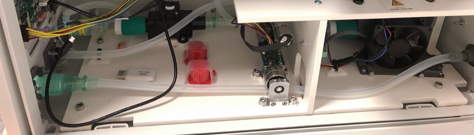
Assembly Overview
If you are reading this article to get a quick overview of the MakAir pneumatics, you may first watch the following video, with which you will understand the fundamentals of the MakAir pneumatic circuit, and its components.
Overall Circuit
As explained in the article of this series on how to ventilate a human patient, a mechanical ventilator may, in the case of invasive ventilation, fully take over the functionality of the lungs. Unless the patient gets ventilated under non-invasive ventilation, the ventilator would then rather assist the patient breathing.
The sheer amount of ventilation modes to support requires the pneumatic circuit to be as versatile as possible (meaning: generic), fully operated by software.
Knowing the human respiratory cycle — where at each phase the lungs inflate with fresh air (inhale phase), then retain that air for a few moments (hold phase), and finally the spoiled air is discharged from the lungs (exhale phase) — a ventilator pneumatic circuit should have the capability to produce air, push it in the lungs (at a certain pressure), hold it inside the lungs, and finally allow the lungs to deflate.
Given what is said above, a ventilator pneumatic circuit would need components to produce air (a turbine), measure pressure & volume (sensors), as well as to cut off, reduce or increase the air flow by controlling the pipe aperture (actuators), meaning no air can pass at all or a certain air flow is allowed.
As explained above, each respiratory cycle is made of three phases: inhale, hold, exhale — as described in a previous article of this series on how to ventilate a human patient.
During each of these three phases, actuators within the air circuit have a specific, changing state, namely:
1. Inhale: air must be pushed in the lungs to reach a P(peak) pressure.
- Inspiratory branch: opened, then closes when
P(peak)is reached (positive pressure); - Expiratory branch: closed;
2. Hold: air must stay in the lungs at a certain pressure, namely P(plateau), down from P(peak).
- Inspiratory branch: closed;
- Expiratory branch: lets a bit of air out and then closes when
P(plateau)is reached (negative pressure);
3. Exhale: air is vented out of the lungs to reach a P(expiratory) or PEEP pressure.
- Inspiratory branch: closed;
- Expiratory branch: lets a almost all air out and then closes when
P(expiratory)is reached (negative pressure);
Each branch — whether inspiratory or expiratory — is independent. It contains a set of actuators and sensors. Those components are described in the next sections.
If you need to refer to a schematic of the full pneumatic system, one is provided at the beginning of an article from this series on the building blocks of a medical ventilator, although not up-to-date on certain details (eg. the expiratory flow sensor is missing).
Inspiratory Branch
The inspiratory branch is made of the components responsible for inflating the lungs, taking in air from the hospital room, filtering it, pressurizing it, and finally directing it in the patient lungs.
The full list of inspiratory branch components is provided right below, in order.
1. Producing air with a blower (turbine & filter)
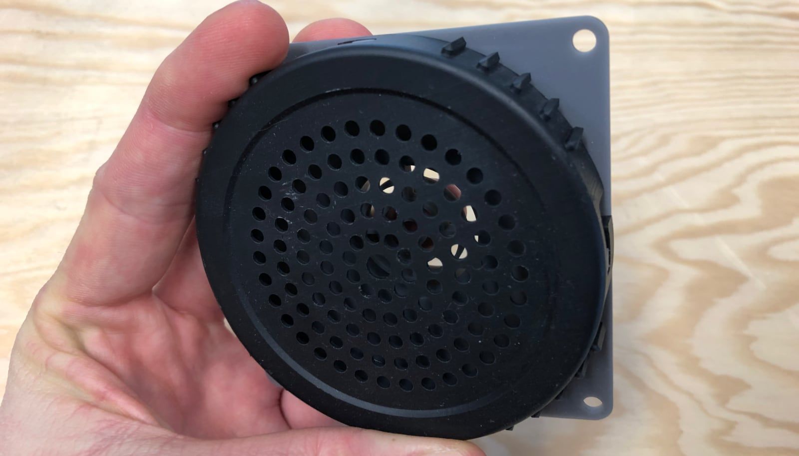
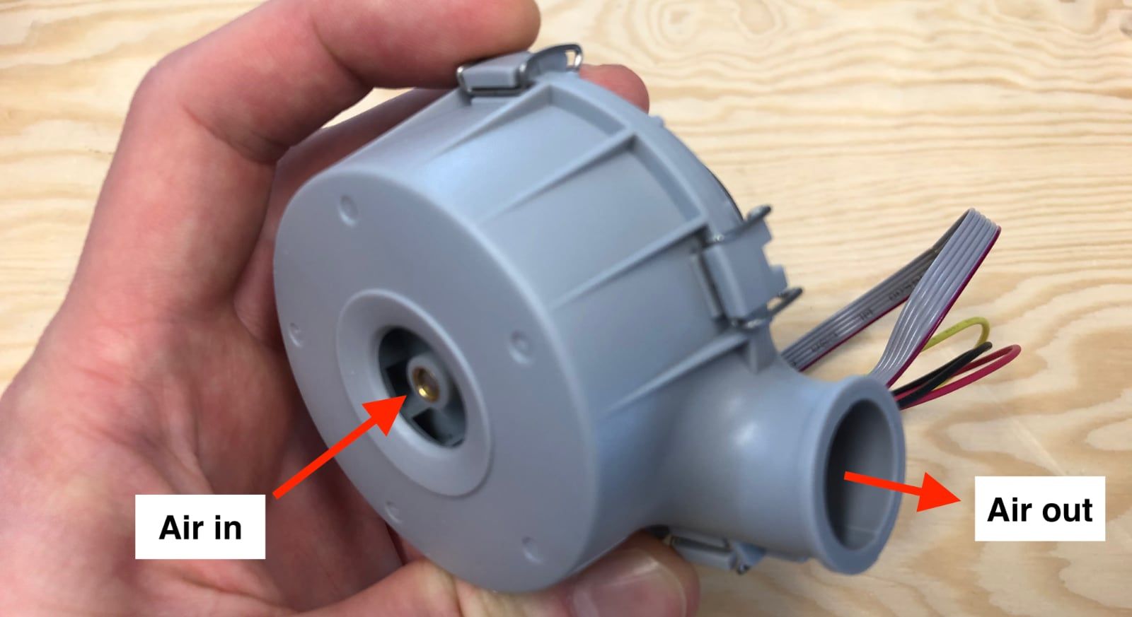
First off, a ventilator needs to gather air from its environment, and pressurize it in order to create a given air flow. A blower turbine is the most convenient component to do that, amongst all available solutions, as it is very compact. One major downside, is that it is noisy, though it can be made silent by caging it in special sound absorbing foam, and noise-insulating its air inlet.
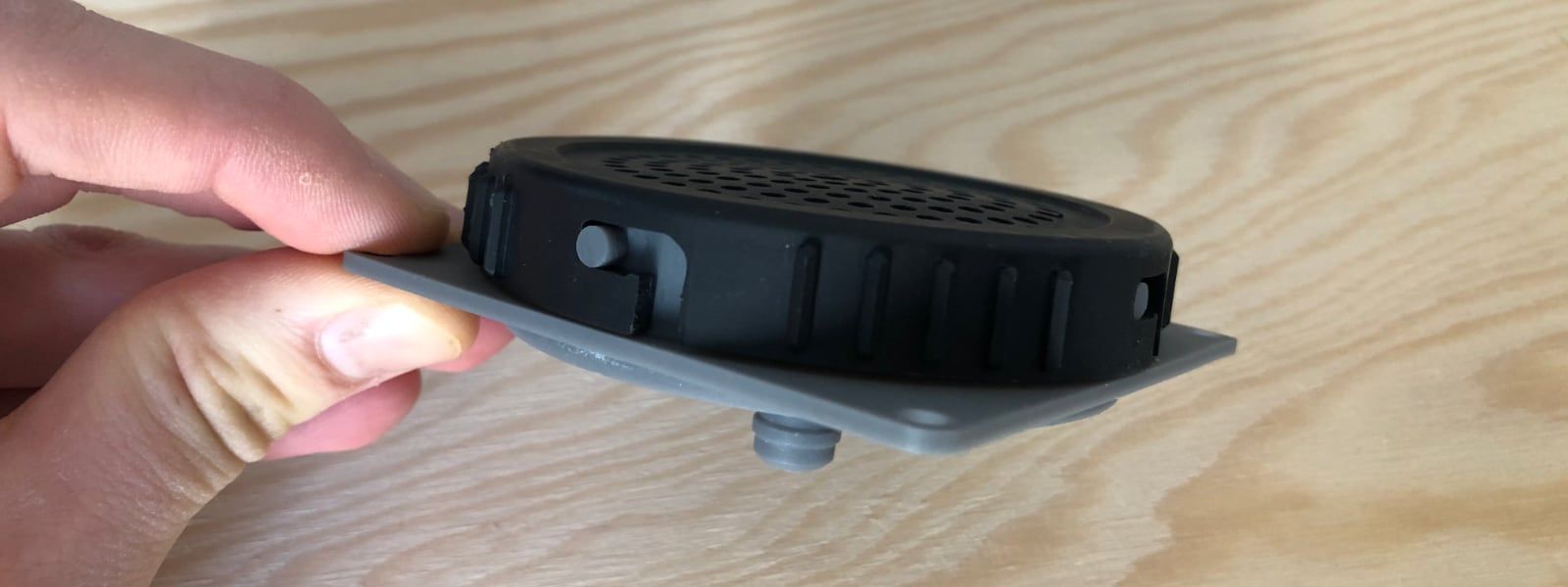
As the air that gets in comes from the external environment (eg. the hospital room), and gets right in the lungs, it may contain pollutants. A filter box must be placed right on the blower inlet. The filter box fits an HEPA 14 filter, capable of filtering germs, viruses, particulate matter, and more.
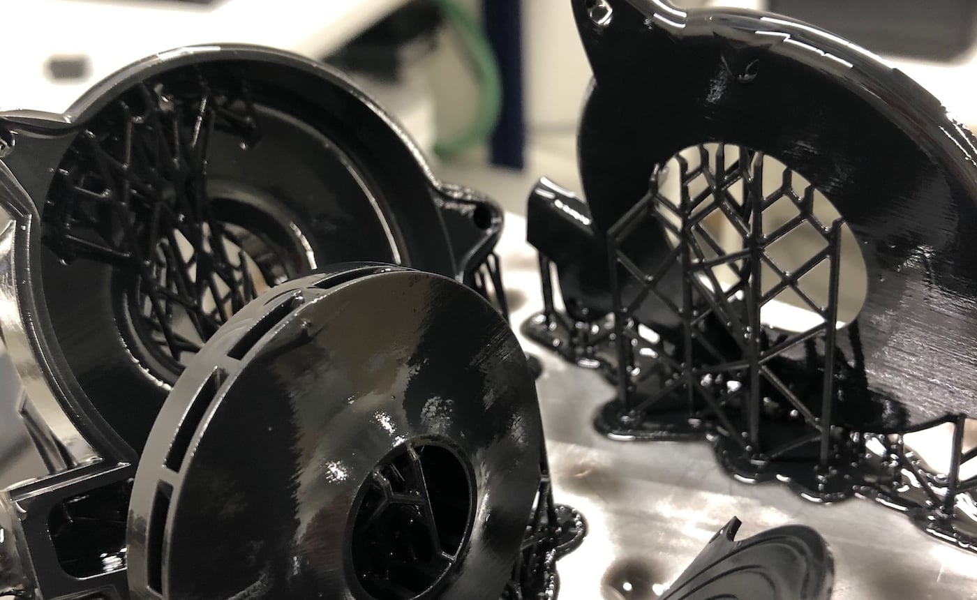
While designing the MakAir ventilator, we tried building our own blower out of DC motors scavenged from a previous drone project. While successful at making it work and producing the required minute volume and pressure, we were not comfortable with the required biocompatibility certification process, as well as complexity of assembly, noise coming from the motor and long-term reliability. If the turbine fails, the ventilator shuts down, potentially harming or killing the patient. Hence, we resorted to existing blowers from the market, matching our specifications.
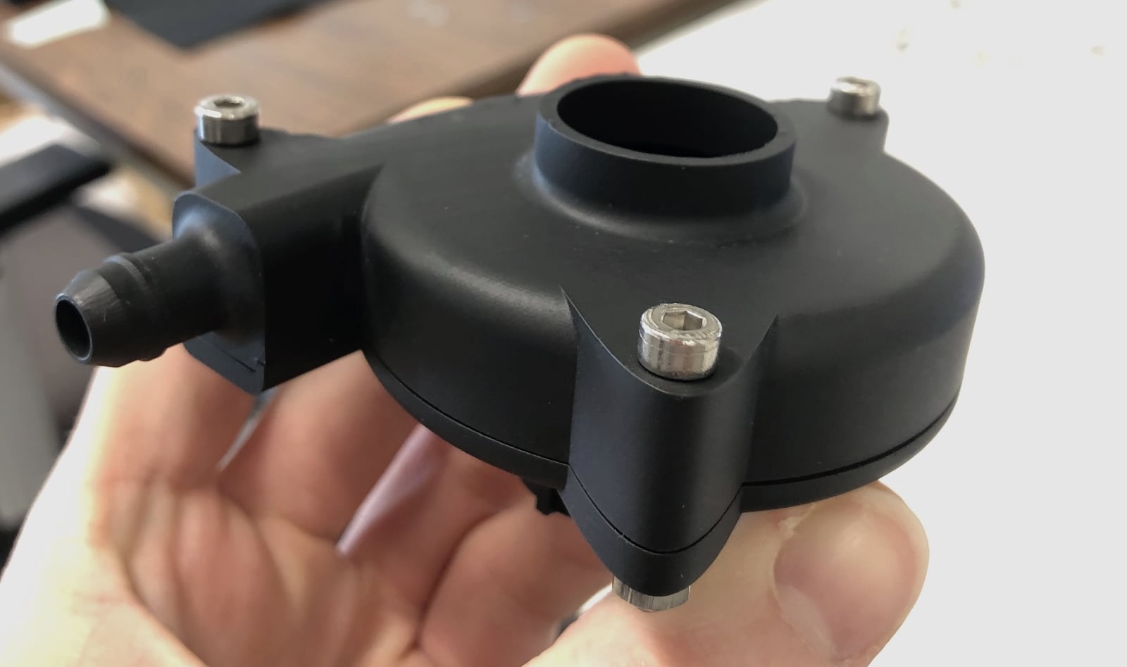
Still, we designed the filter box part ourselves, for which CAD models are available. This filter box would ideally be manufactured using SLS 3D printing, as this would make it biocompatible (if properly post-processed, ie. cleaned).
Filter box:
- ➡️ Final inspiratory filter box CAD model: CAD files, 3D preview.
Blower:
- ➡️ Experimental blower CAD model: CAD files, 3D preview (reminder: we use an on the shelf blower in our production ventilator).
- ➡️ Connector part: Intersurgical straight elastomeric connector 22mm ID.
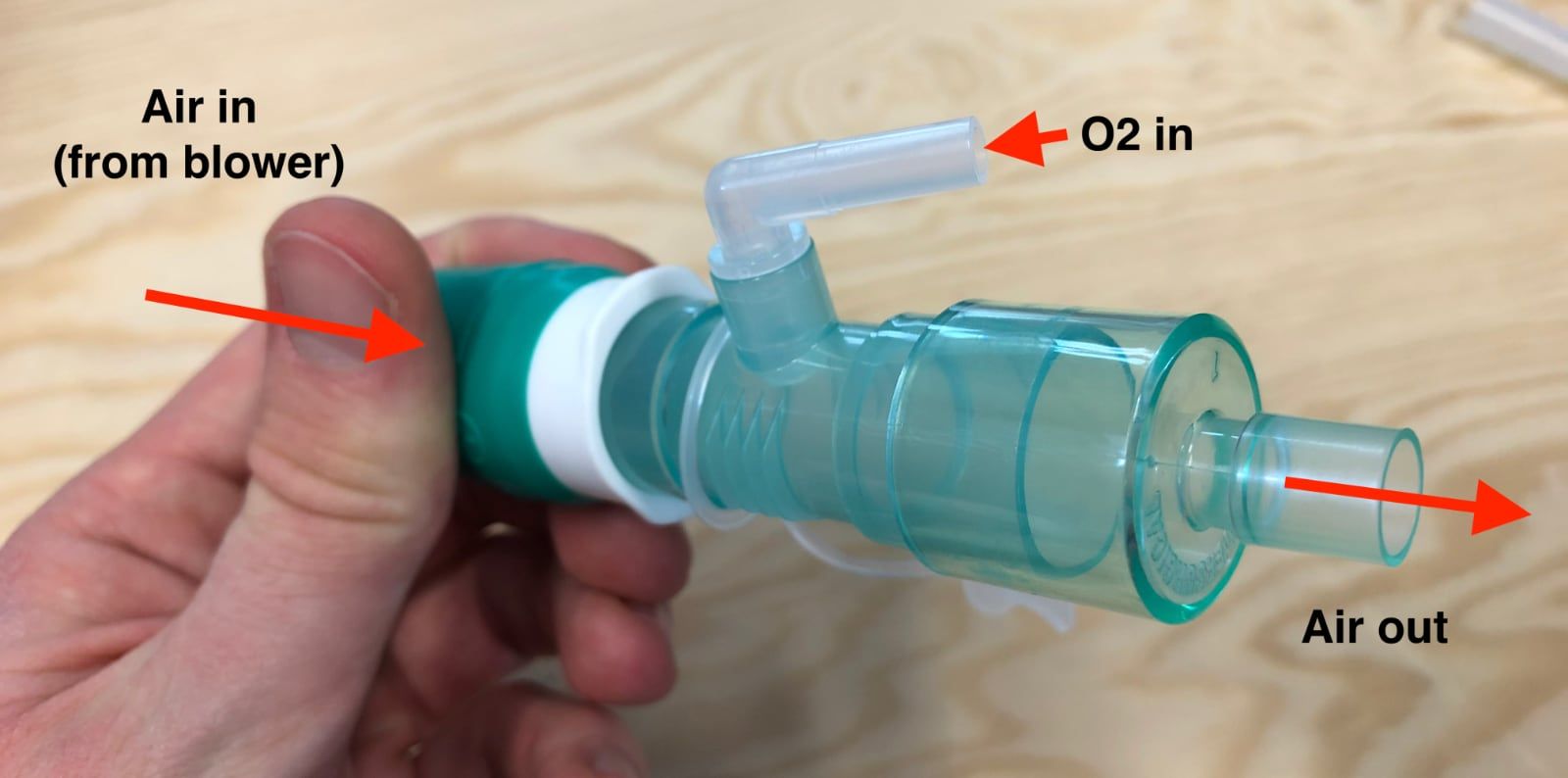
2. Mixing air with oxygen (O2 mixer)
Once the ventilator generates the required air flow from its blower, pure oxygen might need to be mixed (or might not, depending on the patient condition).
Pure oxygen comes from the hospital oxygen system. The oxygen concentration (FiO2) can be adjusted with an oxygen flowmeters. The doctors can then connect the oxygen pipe to the oxygen inlet of the ventilator, which is connected to the internal O2 mixer.
- ➡️ O2 mixer part: Intersurgical straight connector 22mm OD - 22mm ID.
- ➡️ Connector part: Intersurgical straight connector 15mm OD - 22mm ID.
3. Moderating egress air flow (pinch valve)
Once the blown air is enriched in oxygen, we need to be able to control the internal diameter of the flexible pipe, in order to let more or less (or none) air flow pass. A reduced pipe internal diameter means that the air flow is reduced as well. The pinch valve is responsible for that.
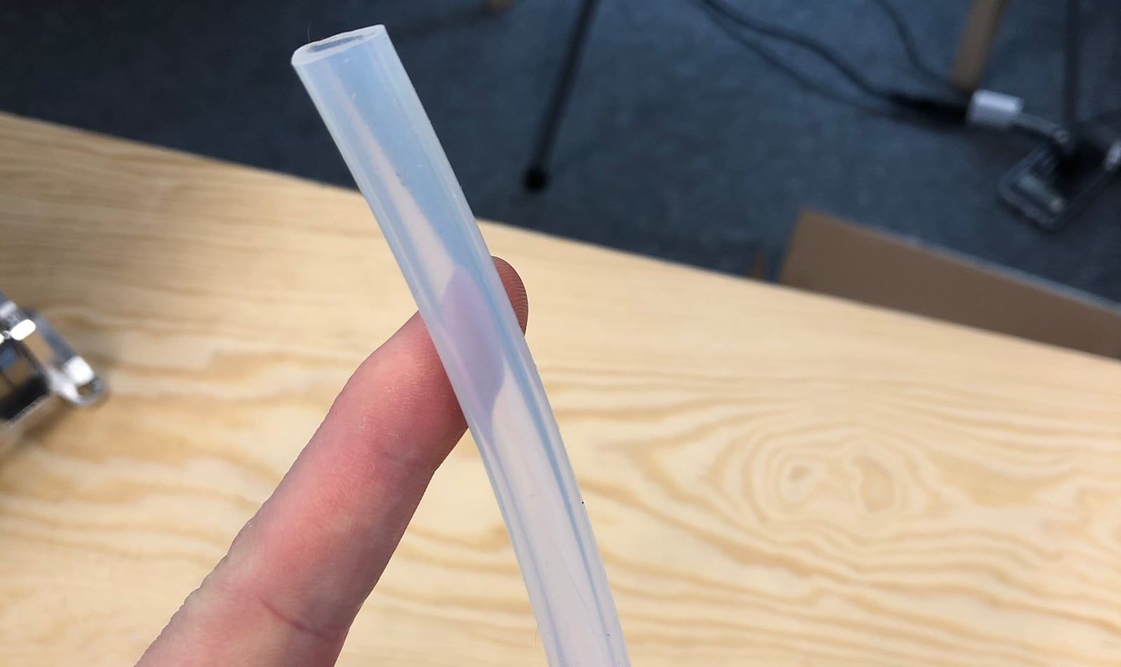
While typical commercial ventilator use more complex components to achieve the same task, we have chosen to keep things simple: the pinch valve is wrapping around the biocompatible flexible pipe in which the air is passing, and applies a variable force on it in order to reduce or increase its aperture.
This method is interesting because it does not introduce pneumatic connections in the system, as we did in earlier prototypes of valves through the project (unsuccessfully). This helps ensure that no leak is introduced, and prevents the air from passing through non-biocompatible materials. All we need here, is a way to press against a pipe, and a flexible silicon hose. Simple.
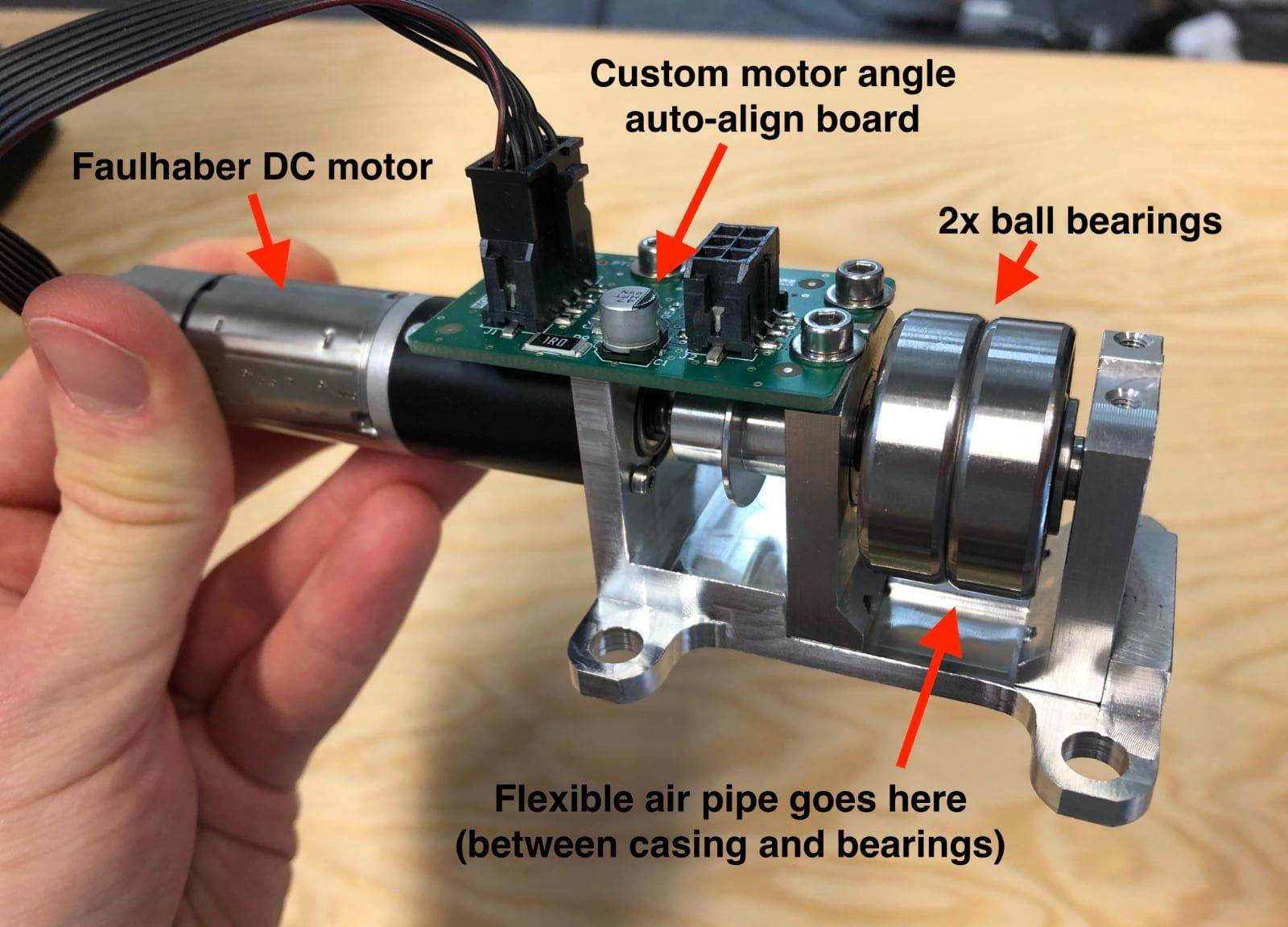
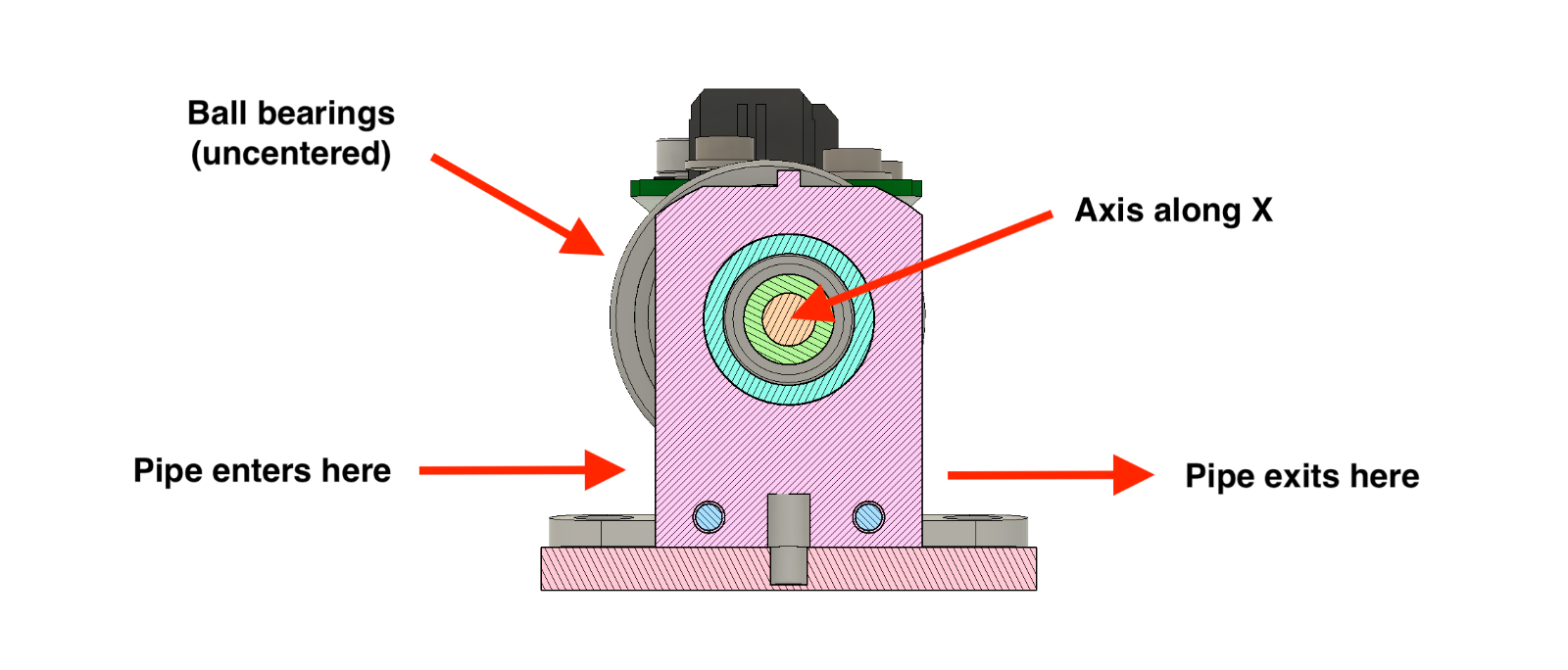
Here is how it works: the pinch valves is controlled by software, and takes a target angle as its sole input. An angle relates to how much pressure is applied on the pipe. A Faulhaber DC servo motor rotates to the target angle, which moves two ball bearings and presses the pipe more or less.
We recommend using industrial-grade high-quality servo motors, and ditch cheaper hobbyist servo motors, as they would not last the required half a million cycles to ventilate a COVID-19 patient over the course of 2 weeks.
Ball bearings have been chosen in order to limit friction between materials to a minimum, as the bearings are “rolling” on the pipe, instead of “rubbing” against it. This reduces strain on the DC motor, saves battery and minimizes wear. In order to apply pressure given an angle, the ball bearings are held on an axis which is not centered, that way rotating the axis across Y (horizontal) would create a variable pressure across Y (vertical).
You may wonder as well why is the chassis made of stainless steel. We could have chosen traditional plastic instead, though note that in this case the plastic would have to be high-density and rigid. Indeed, the pressure applied is such that we have observed 3D printed plastic parts to change shape and ultimately break. Going to metal was an easy fix for us, but you may as well find a strong plastic as an alternative.
- ➡️ Pinch valve DC motor: Faulhaber 2232 S 024 BX4 CSD.
- ➡️ Pinch valve bearings (large): SKF 30 mm W 6200-2RS1.
- ➡️ Pinch valve bearings (small): SKF 16 mm W 625-2RS1.
- ➡️ Pinch valve chassis CAD model: CAD files, 3D preview.
- ➡️ Pinch valve board PCB model: PCB model files.
4. Sensing egress air flow (flow sensor)
In order for the algorithm to to control the air flow and pressure via the pinch valves, it needs to be fed real-time measurements on the air flow in the circuit.
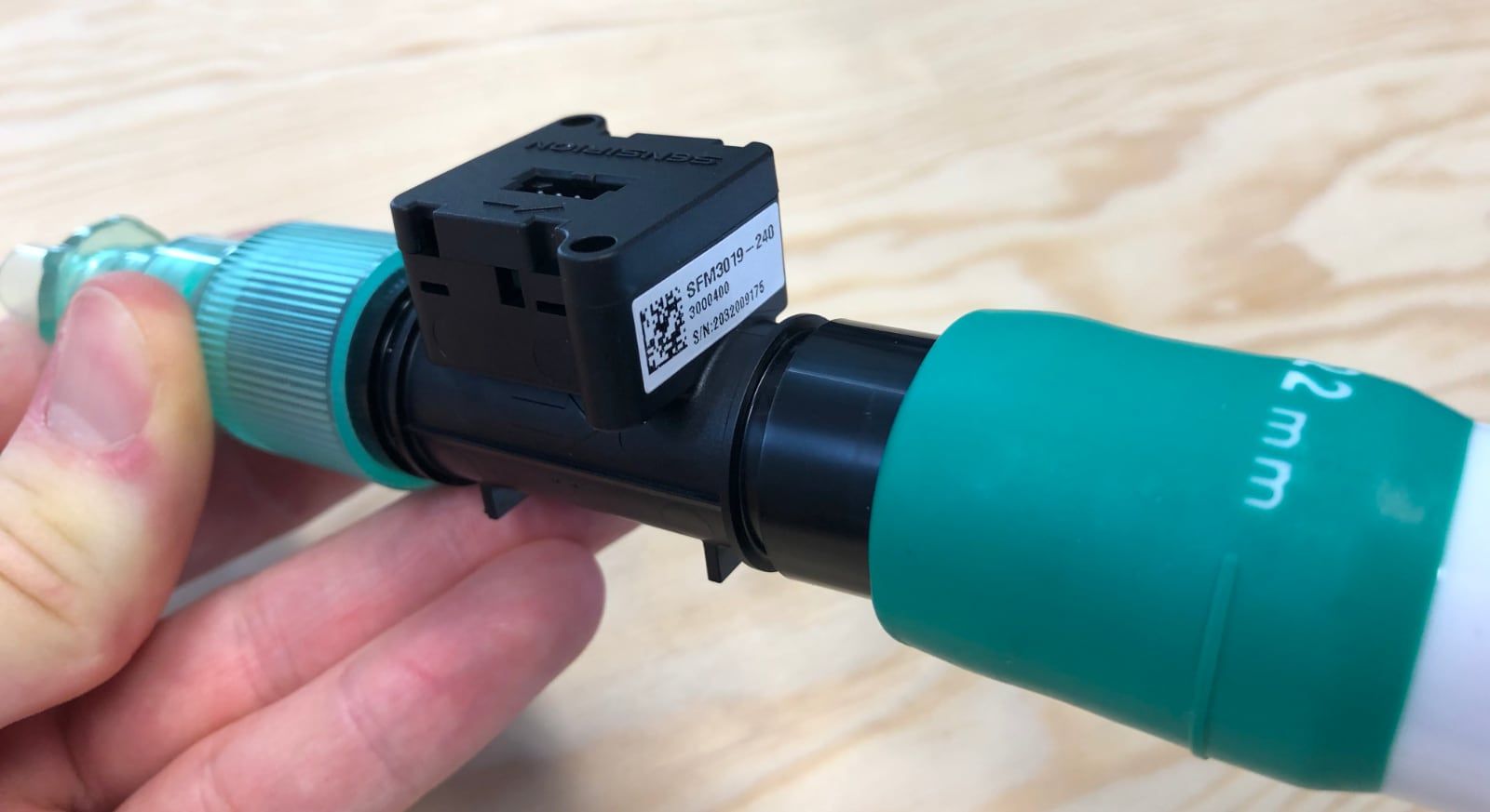
The MakAir includes a Sensirion SFM 3019 mass flow meter sensor near the end of its inspiratory branch, right after the pinch valve. This sensor provides measurements in liters per minute (of air).
- ➡️ Mass flow meter sensor: Sensirion SFM 3019.
- ➡️ Connector: Intersurgical straight connector 15mm ID - 22mm ID.
5. Preventing spoiled air reflux (non-return valve)
When a sick patient breathes on a mechanical ventilator, the exhaled air from their lungs could contain viruses or other germs, that we do not want to spread everywhere in the pneumatic circuit. Especially, if the ventilator is to be re-used on another patient later.
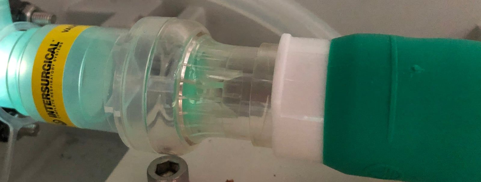
The non-return valve lets air pass in a direction, but not the other. This component, here from Intersurgical, eases the sterilization work of maintenance personnel after use, as it protects the inspiratory branch from contamination. That is, up to the pinch valve, as the blower-to-pinch valve section is protected anyway due to constant positive pressure.
The expiratory branch, as we will see later, is designed to be contaminated anyway, as there is no other way around it. Though, as the branch is simple and made of a single pipe and a single flow sensor, it is deemed acceptable to throw everything away and replace the whole branch with new parts.
Note that the non-return valve was not shown in the overview video above, as the ventilator functions normally without it. Though, it is very desirable, and could be mandatory for medical certification purposes.
- ➡️ Non-return valve: Intersurgical one-way directional valve 22M flow in - 22F flow out.
6. Sensing egress air pressure (pressure sensor)
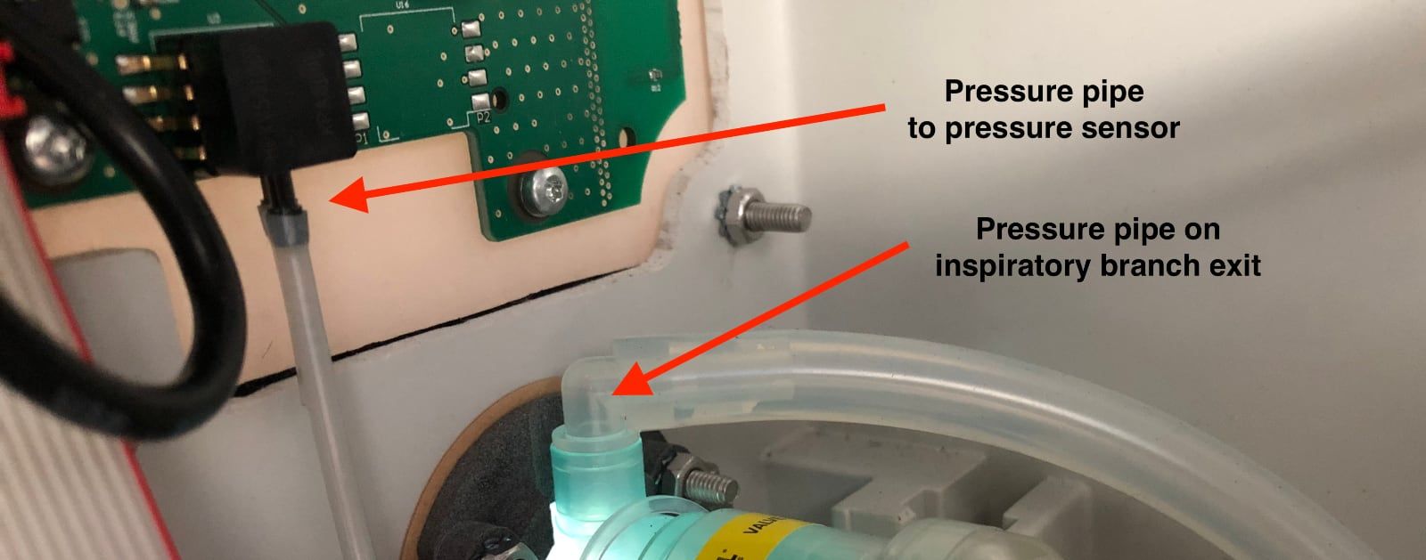
Just as with the air flow sensor, algorithms need to know the current pressure in the lungs, using a pressure sensor. This sensor is mounted on the motherboard, and a small pipe connects it to the air circuit.
As this sensor does not measure the pressure in the inspiratory branch, but rather in the lungs, it needs to be located after the non-return valve. That is, as near as possible to the patient lungs, if we were to look at a schematic of the pneumatic circuit.
An Intersurgical-made biocompatible straight connector is used to connect the pressure sensor component on the motherboard, to the air circuit. It is very similar to the Intersurgical part used for the O2 mixer.
- ➡️ Pressure extractor: Intersurgical straight connector 22mm OD - 22mm OD.
- ➡️ Exit fit: Intersurgical straight connector 22mm OD - 22mm ID.
Expiratory Branch
The expiratory branch is made of the components responsible for deflating the lungs, taking in air from the lungs, filtering it, and exhausting it to the hospital room.
The full list of expiratory branch components is provided right below, in order.
1. Sensing ingress air flow (flow sensor)
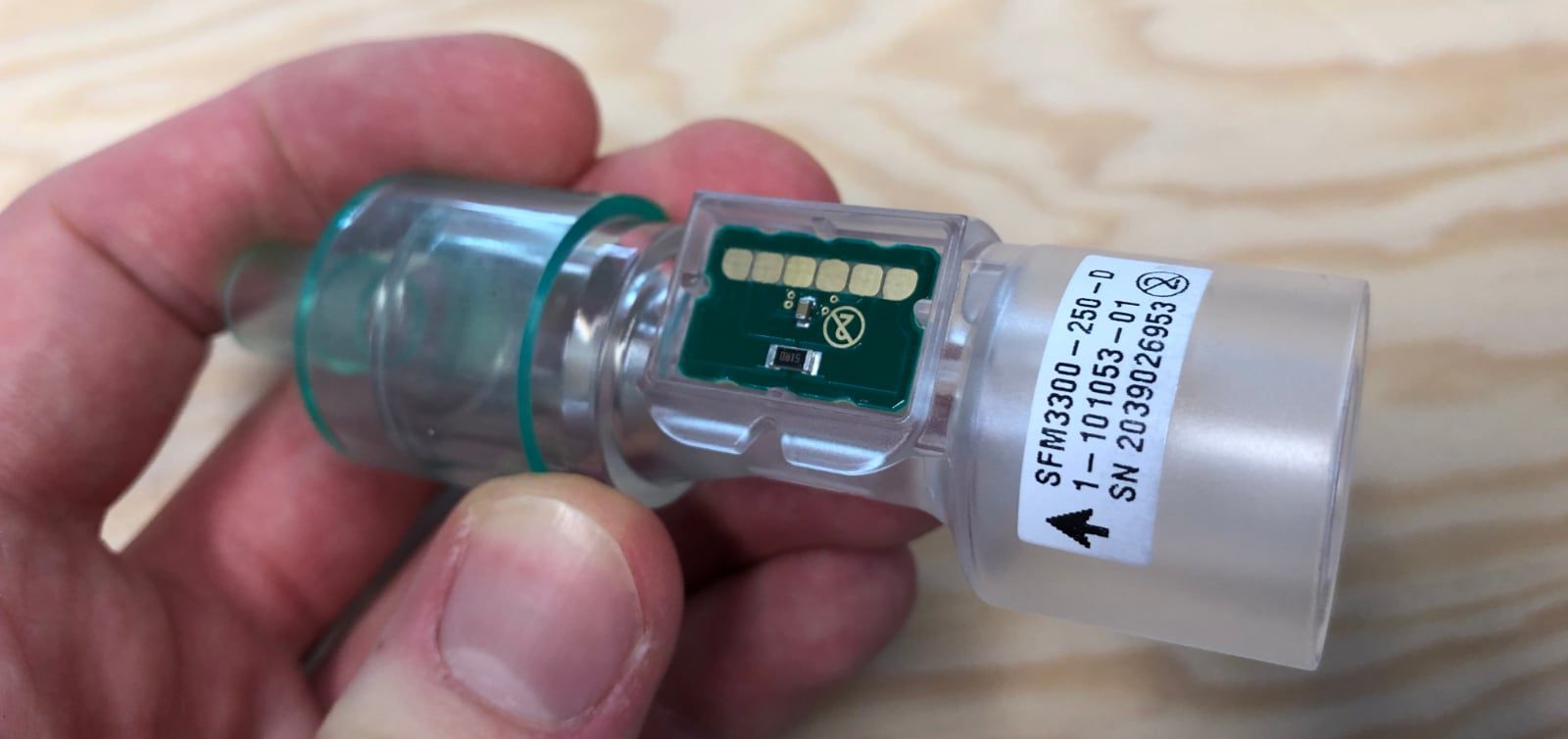
As with the egress air flow on the inspiratory branch, the ingress air flow must be measured on the expiratory branch, and fed to the algorithm. There, a Sensirion SFM 3300D digital flow meter is used.
As air coming from the patient lungs circulate within the expiratory branch, all components on its path could be contaminated with viruses and germs. This means that this branch would need to be sterilized after each use on a patient, or more simply put, all the components on that branch could be thrown away and replaced with brand new components.
This sensor is fortunately much less expensive than the inspiratory branch sensor, costing about 40 EUR, and thus we recommend that it is replaced after each use.
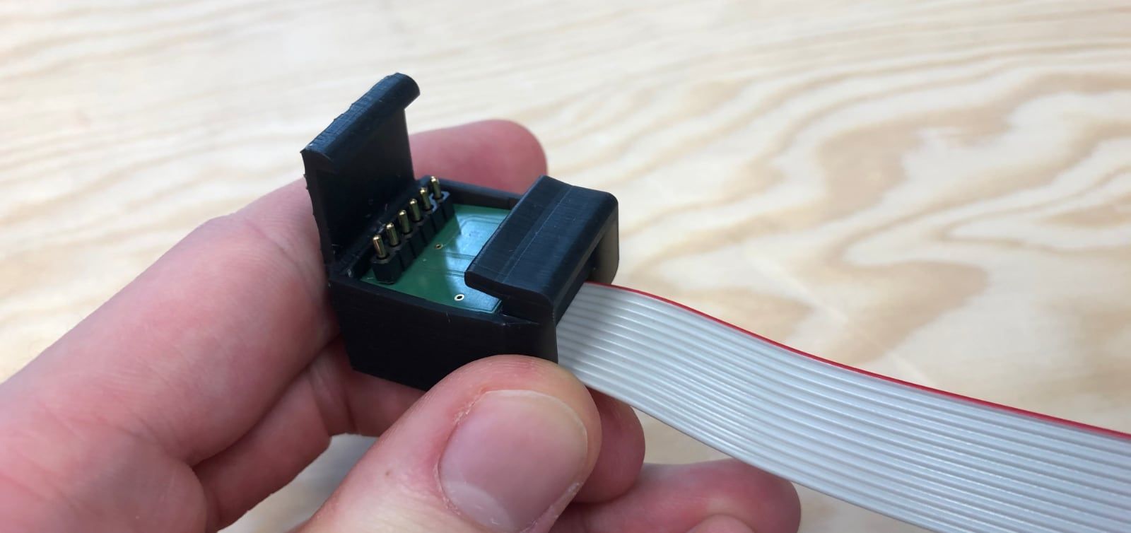
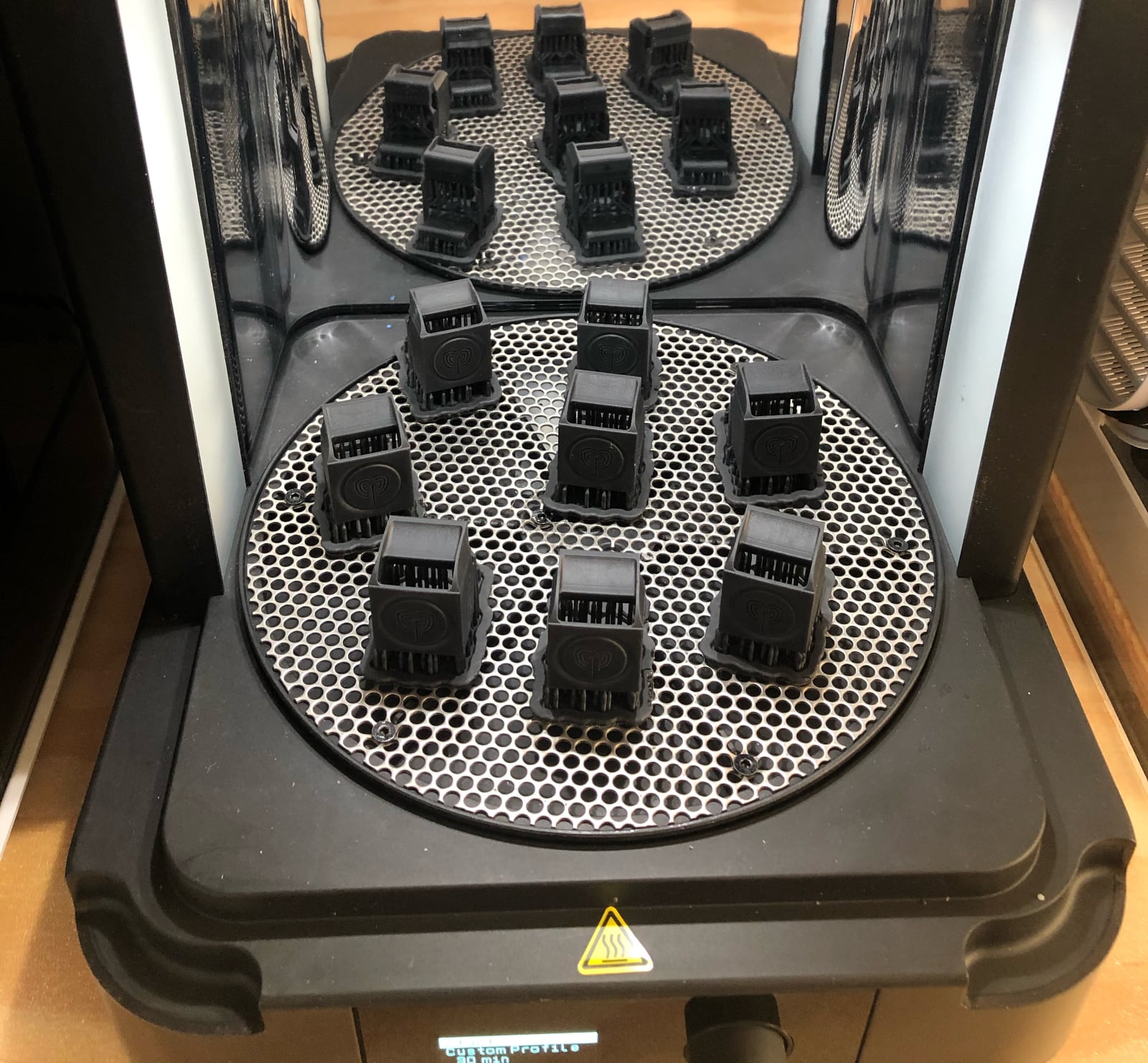
To ease with replacement and maintenance, a 3D printed connector hat was designed, which snaps onto the sensor and can be easily removed. The connector hat contains a PCB which presses electrical connectors on the sensor PCB, helping connecting the sensor to the motherboard.
Sensor:
- ➡️ Digital flow meter sensor: Sensirion SFM 3300D.
- ➡️ Entry fit: Intersurgical straight connector 22mm OD - 22mm ID.
- ➡️ Connector: Intersurgical straight connector 15mm OD - 22mm ID.
Connector hat:
- ➡️ Connector hat CAD model: CAD files, 3D preview.
- ➡️ Connector hat PCB model: Eagle files.
2. Moderating ingress air flow (pinch valve)
This section works exactly as the one with the pinch valve on the inspiratory branch. The ingress air flow needs to be moderated using a pinch valve as well.
As the pinch valve is exactly the same as on the inspiratory branch, please refer to explanations and pictures from the inspiratory pinch valve section above.
3. Venting out ingress air flow (filter)
During the exhale phase, air is vented outside of the patient lungs into the expiratory circuit, and ultimately out of the ventilator.
Given that the air might be contaminated, it needs to be filtered using the same HEPA 14 filter as used on the inspiratory filter.
Note that this expiratory filter box is almost the same as the one from the inspiratory branch. The connector is different, as the expiratory filter box connects to the flexible pipe.
- ➡️ Final expiratory filter box CAD model: CAD files, 3D preview.
Closing Notes
This article was the fourth of a series on the MakAir story, providing insider details on the project, medical knowledge on the state of the art of mechanical ventilation, as well as in-depth engineering explanations on how we designed our ventilator algorithms and electronics. The overall goal of this series of articles is to build the legacy of the MakAir project.
Coming up with the air circuit described in this article could only be achieved by taking a trial and error approach. The MakAir engineering team started experimenting with 3D printed parts (eg. the O2 mixer) but ultimately settled on using on the shelf biocompatible parts manufactured by Intersurgical, except for some parts which are not in contact with air (eg. the 3D printed expiratory flow sensor hat, or the CNC-machined pinch valve metal chassis).
Also, I’m always available to answer questions, please ask them in the comments section of this article!
🇫🇷 Written from Nantes, France.